Camera tracking system for a virtual television or video studio

a technology for virtual televisions and video studios, applied in television systems, instruments, digital computer details, etc., can solve the problem of requiring a relatively high effort in measurement techniques for known systems, and achieve the effect of quick and reliable determination of position and orientation

Inactive Publication Date: 2005-02-15
GMD-FORSCHUNGSZENTRUM INFORMATIONSTECHNIK
View PDF26 Cites 33 Cited by
  • Summary
  • Abstract
  • Description
  • Claims
  • Application Information

AI Technical Summary

Benefits of technology

It is therefore an object of the present invention to provide a camera tracking system that precisely, quickly and reliably determines the position and orientation of a camera that is adapted to be moved freely in a room.

Problems solved by technology

This known system requires a relatively high effort in measurement techniques.

Method used


Image

  • Camera tracking system for a virtual television or video studio
  • Camera tracking system for a virtual television or video studio
  • Camera tracking system for a virtual television or video studio

Examples


Embodiment Construction

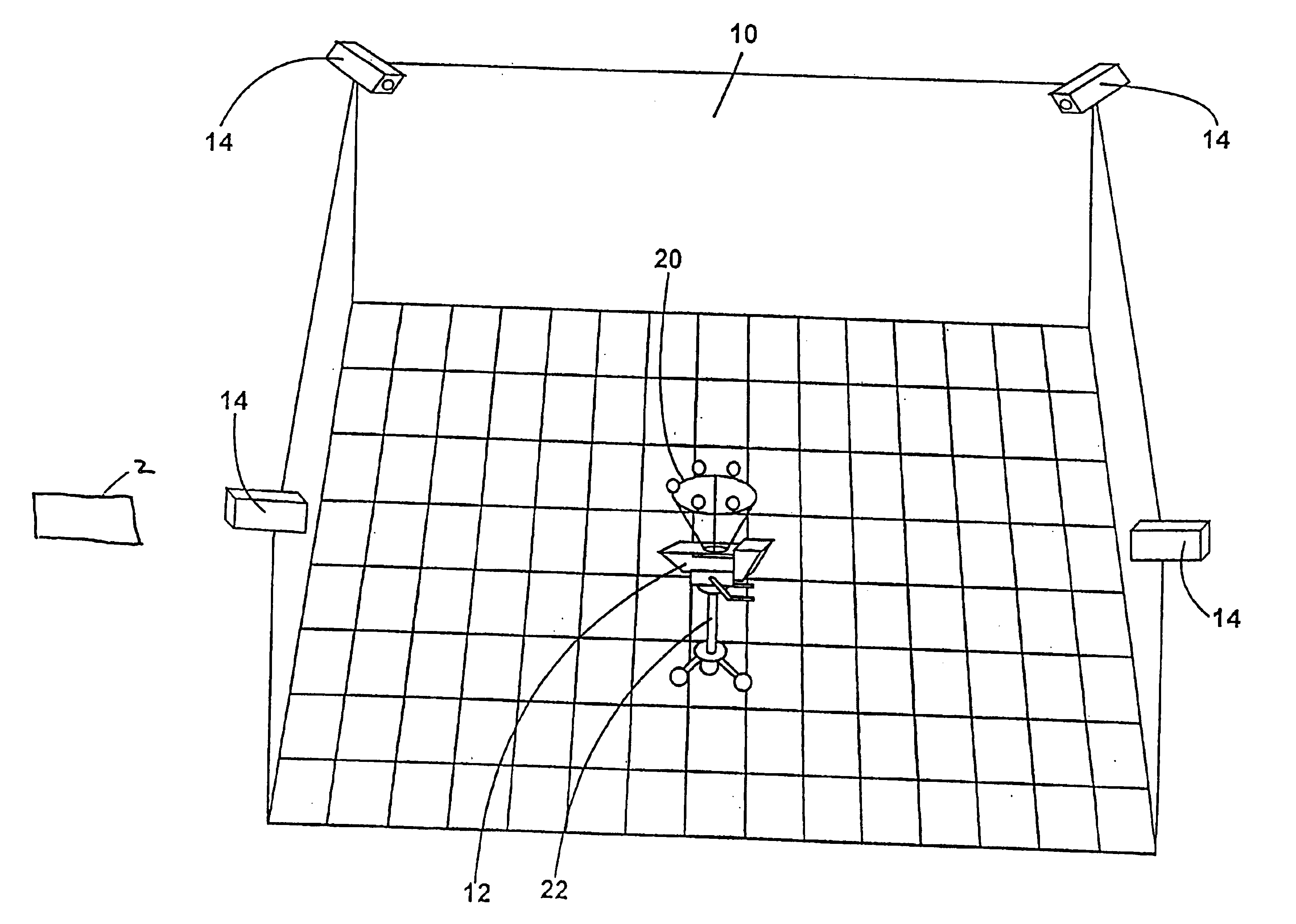
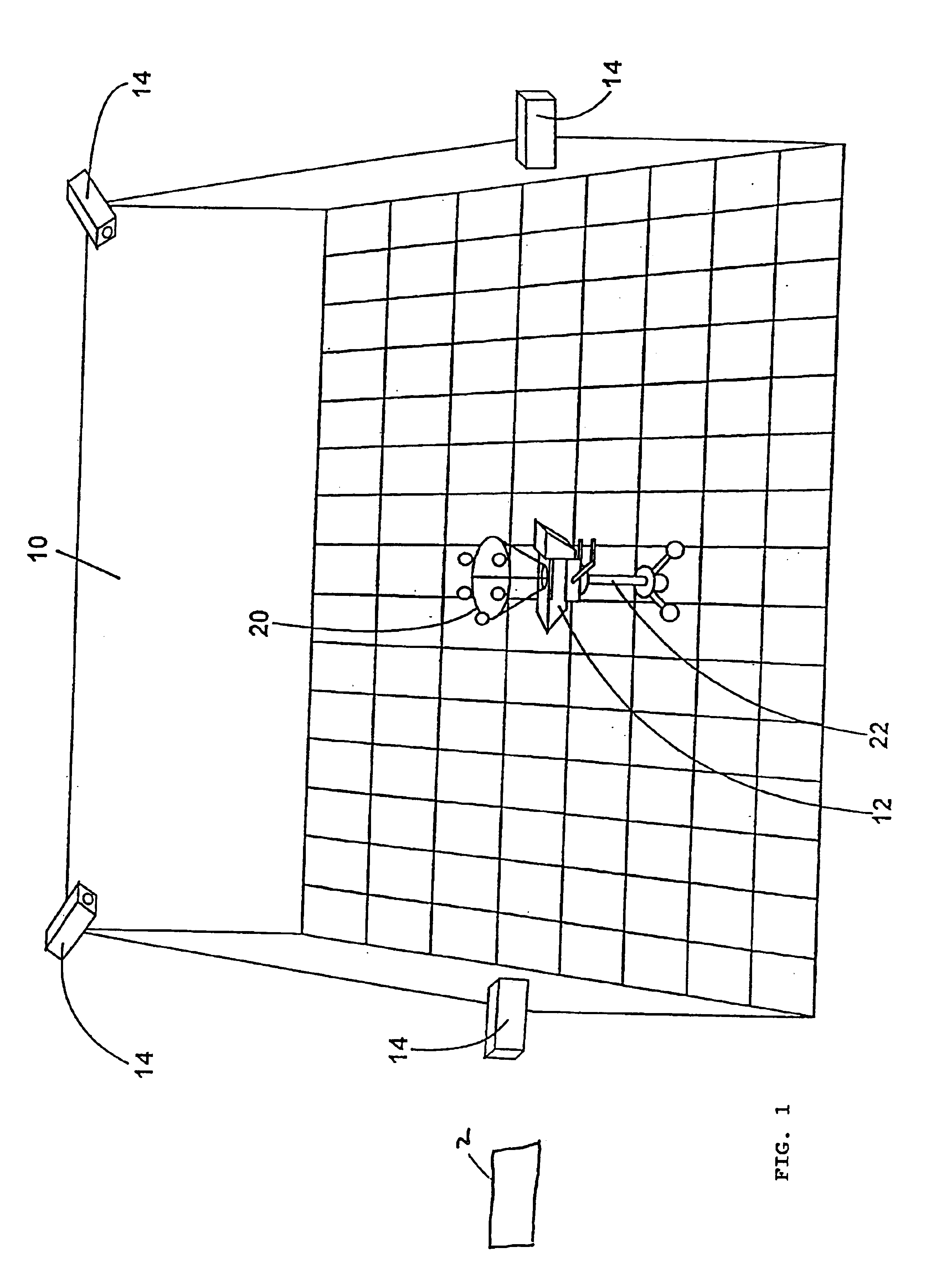
FIG. 1 illustrates a blue-room studio 10 with a (studio) camera 12 and four detecting cameras 14 suspended fmm the ceiling. The detecting cameras 14 are suspended as high as possible and as far as possible from the center of the blue-room studio and are distributed over the blue-room studio such that they detect the studio fmm different angles of view.

The detecting camera 14 used here is a commercial CCD TV camera for black-and-white shooting that was rearranged so as to be able to receive infrared light. Specifically, the infrared filter usually present in commercial CCD TV cameras can be removed and replaced with a filter filtering visible light and only transmitting infrared light. This restructuring yields a low-cost detecting camera that is adapted to detect light emitted in the infrared range particularly well. The light spots detected by the CCD chip are then supplied to a computer 2 for evaluation.

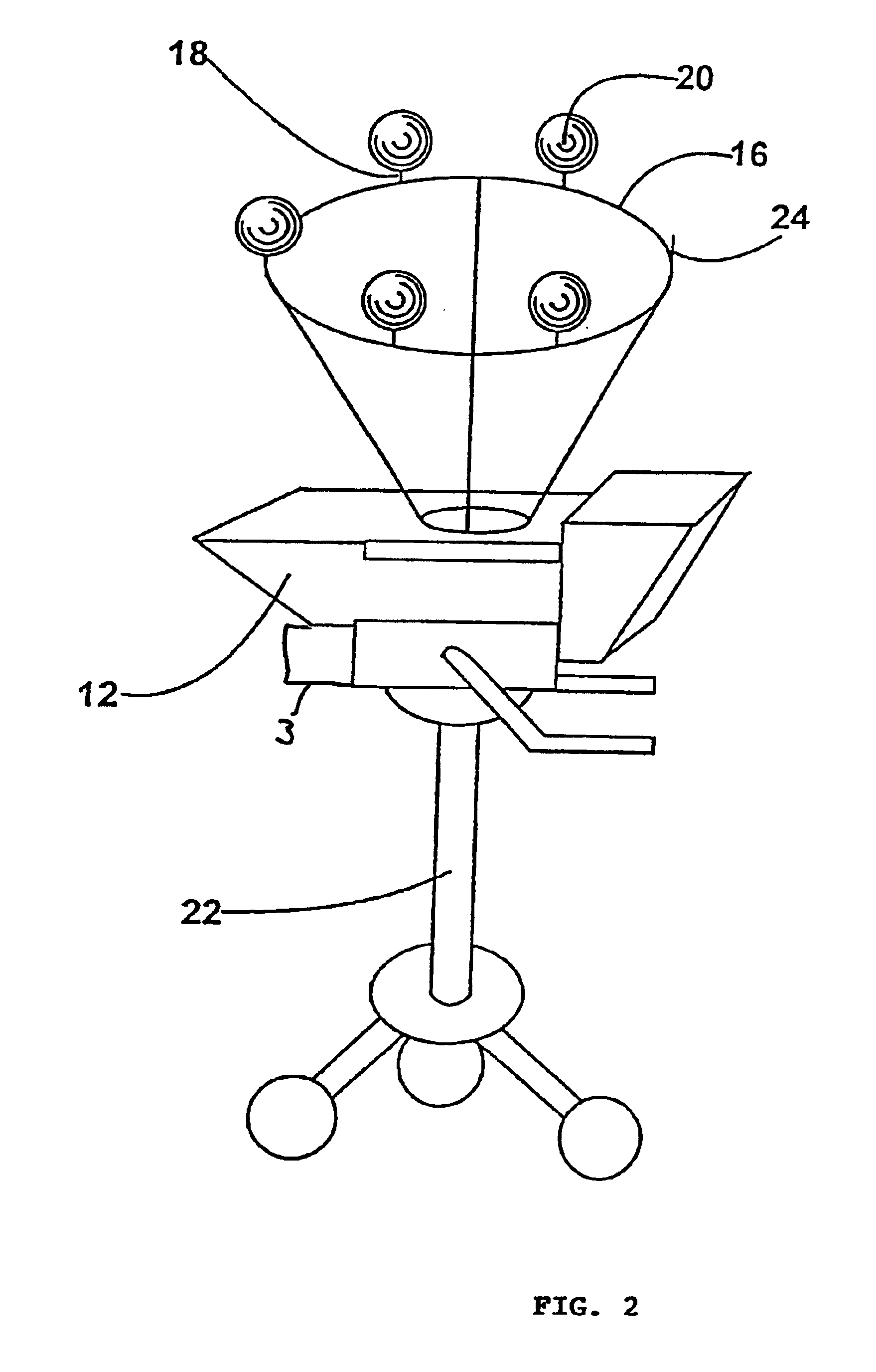
At a distance of about 50 cm, a ring 16 is mounted to the (studio) camera 12, ...


PUM


Abstract

A camera tracking system for a virtual television or video studio is provided. The camera tracking system is used to determine the position and/or orientation of recording cameras and comprises emitter devices for emitting electromagnetic radiation. The emitter devices can be mechanically coupled to the recording camera. The camera tracking system further comprises detecting devices for detecting the position of the emitter devices on the basis of the electromagnetic radiation emitted by the emitter devices, each detecting device being able to detect several emitter devices. A computer unit evaluates the electromagnetic radiation detected by the detecting devices and emitted by the emitter device, and determines the position and/or orientation of the emitter devices in relation to the detecting devices.

Description

BACKGROUND OF THE INVENTION1. Field of the InventionThe present invention relates to a novel camera tracking system for a virtual television or video studio.2. Description of the Background ArtIn producing virtual film or video sequences, the images recorded by a camera, for example, images of a person, are combined in a special device with a background (electronic set) that is not really present (i.e. virtual), or with other details generated in the device (a so-called virtual studio). In order to integrate the person filmed by the camera into the virtually generated background with precision and positional accuracy, the respective actual position and orientation of the recording camera (studio camera) must be known.Conventionally, the position of the recording camera has been calculated, starting from a zero position, by measuring the distance traveled and the Orientation of the camera has been determined by measuring the pivot angle, the pitch angle, and the rolling angle using c...

Claims


Application Information

Patent Timeline
Patent Type & Authority Patents(United States)
IPC IPC(8): G01S1/00G01S1/70G01S1/02G01S13/00G01S13/75G01S5/16G01S5/00H04N5/222H04N5/272
CPCG01S1/022G01S1/70H04N5/222G01S5/163G01S13/75G01S5/16
Inventor FEHLIS, HENDRIKMAYER, THOMASSCHNEPF, UWEMIKA, THORSTEN
Owner GMD-FORSCHUNGSZENTRUM INFORMATIONSTECHNIK
Why Eureka
Try Eureka