Lock enhancing device

a technology of enhancing device and locking mechanism, which is applied in the field of locks, can solve the problems of reducing the service life of the lock, so as to maximize the resistance to over twisting or impact, reduce the direct burden of impact, and effectively share the strength of the door

Inactive Publication Date: 2005-02-22
PATH LINE NGS HLDG
View PDF19 Cites 6 Cited by
  • Summary
  • Abstract
  • Description
  • Claims
  • Application Information

AI Technical Summary

Benefits of technology

A main object of the present invention is to provide a door lock comprising a lock enhancing device which is arranged to engage with a door on which the door lock is mounted so as to effectively share the strength of the door to maximize resistibility to over twisting or impact to the knob assembly of the door lock. In other words, the present invention considerably distributes externally applied damaging forces to the door so as to minimize a direct burden of impact borne by the knob assembly.
Another object of the present invention is to provide a door lock which comprises a lock enhancing device comprising a latch guider adapted to transversely bias against a front protective housing and a rear knob frame of the knob assembly so as to resist a damaging transverse or twisting force applied thereto. Moreover, the latch guider helps in distributing externally applied forces to the door.
Another object of the present invention is to provide a door lock wherein the front protective housing comprises a reinforced base in order to effectively resist external damaging force applied to the door lock so as to increase the overall security thereof. Moreover, the front protective housing is also reinforced in term of its structure so as to be capable of substantially preventing a distortion when subjected to the external damaging force.
Another object of the present invention is to provide a door lock which comprises a lock enhancing device comprising a coupling arm rearwardly extended from the actuation unit to connect the front protective housing with the rear knob frame via a door latch assembly sandwiched therebetween so as to increase the connection strength of the door lock of the present invention. In other words, the front protective housing and the rear knob frame are securely connected to resist external damaging twisting forces or impacts.
Another object of the present invention is to provide a door lock comprising a lock enhancing device which does not involve complicated or expensive mechanical components so as to minimize the manufacturing cost and the selling price of the present invention in order that the door lock of the present invention can be widely accepted by public, thus increasing their security awareness.

Problems solved by technology

Unfortunately, very often, the front protective housing is not strong enough both in terms of the materials used and its structure so that an intentional trespasser, by strongly twisting the actuation unit or vigorously breaking the front protective housing, can be able to destroy the door lock and open the door.
Even though the front protective housing is not broken altogether by the external force, such a substantial impact may have caused considerable distortion to it which then becomes extremely vulnerable to future damages.
Second, the connection between the front protective housing and the rear knob frames is usually not strong enough so that when a trespasser applies vigorous impact to the door lock, the connection between the first and the rear knob assembly will be broken altogether and, as a result, the front protective housing and the rear knob frame and the actuation unit may detach from the door and leave the door unlocked immediately.
As can be seen from these figures, there exist a very high official standard expected from a qualified door lock, and in respect of this, most conventional door locks fail to achieve the required standard.

Method used


Image

  • Lock enhancing device
  • Lock enhancing device
  • Lock enhancing device

Examples


Embodiment Construction

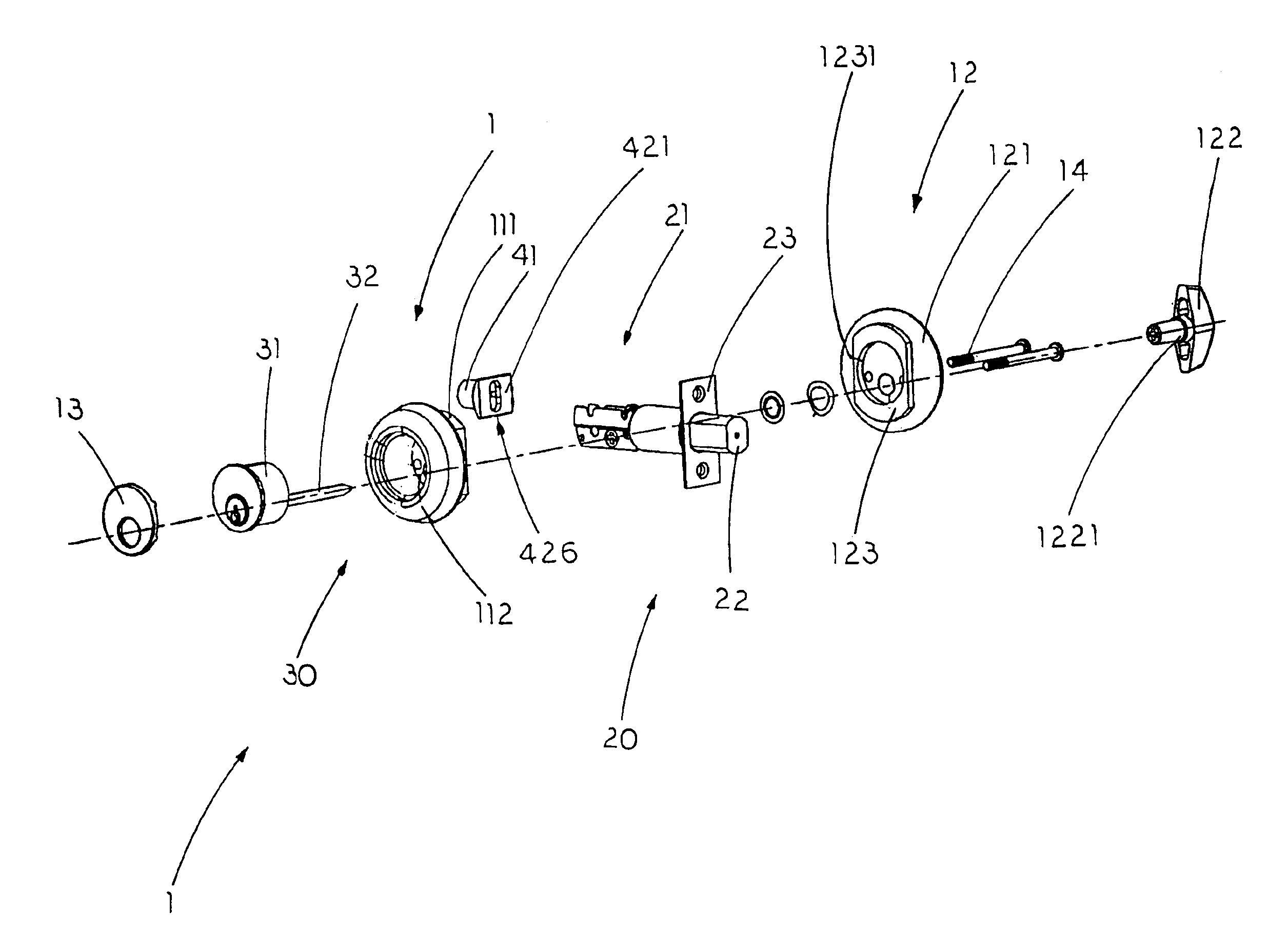
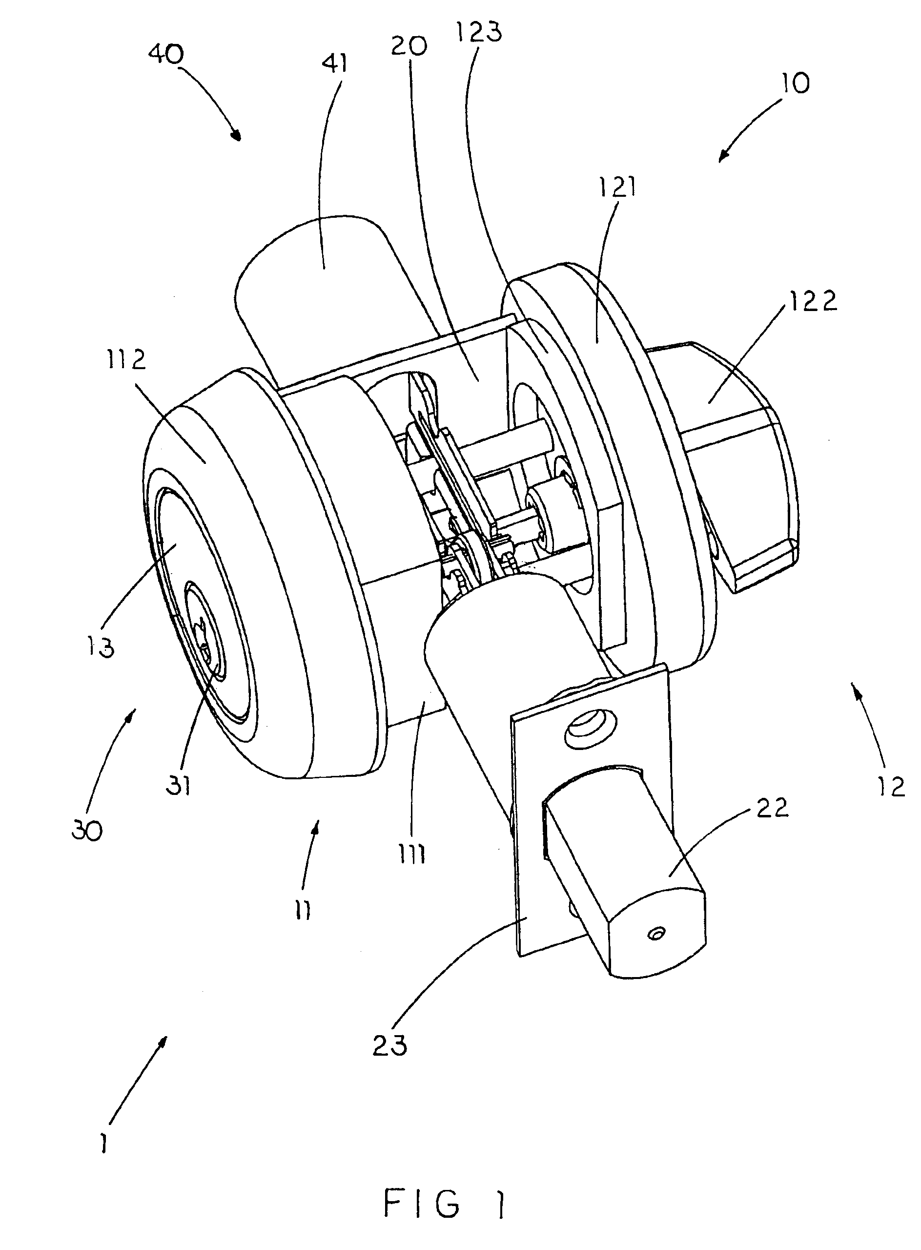
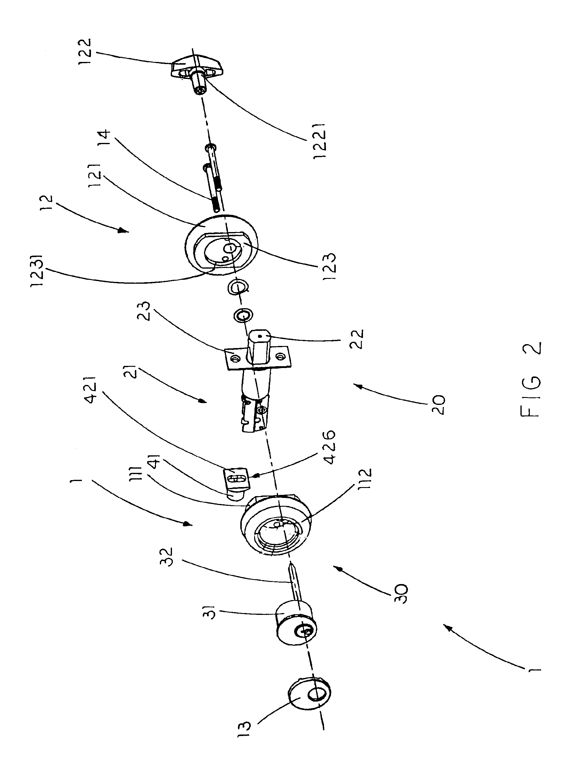
Referring to FIG. 1 and FIG. 2 of the drawings, a lock 1 for locking a door panel to a door frame according to a preferred embodiment of the present invention is illustrated. According to the preferred embodiment, the lock 1 comprises a knob assembly 10, a door latch assembly 20, an actuation unit 30, and a lock enhancing device 40.

The knob assembly 10 comprises a front protective housing 11 and a rear knob frame 12 adapted for being mounted on a front and a rear side of the door panel respectively to form a lock cavity therebetween, wherein the door latch assembly 20, the actuation unit 30 and the lock enhancing device 40 are supported in the lock cavity.

The front protective housing 11, preferably made of metallic materials such as brass, comprises a reinforced base 111 and a side boundary 112 frontwardly and peripherally extended therefrom to define a receiving cavity between the reinforced base 111 and the side boundary 112, wherein the actuation unit 30 is adapted to be mounted ...


PUM


Abstract

A lock for locking a door panel to a door frame, which includes a knob assembly comprising a front protective housing and a rear knob frame defining a lock cavity therebetween in the door panel; a door latch assembly including a latch actuation member transversely disposed within the lock cavity and a locking latch connected to the latch actuation member in a slidably movable manner; an actuation unit to actuate the door latch assembly; and a lock enhancing device which includes a reinforcing member for substantially mounting to the door panel between the front and the rear side thereof, and a latch guider integrally extended from the reinforcing member within the lock cavity to couple with an inner end portion of the latch actuation member so as to substantially retain the latch actuation member within the lock cavity in position.

Description

BACKGROUND OF THE PRESENT INVENTION1. Field of InventionThe present invention relates to locks, and more particularly to a lock enhancing device which is arranged to reinforce the strength of conventional locks so as to prevent them from being easily damaged, thus failure to provide sound security.2. Description of Related ArtsA wide variety of locks have been widely used for security purposes. A conventional door lock which is incorporated in a door usually comprises an actuation unit which has a key slot formed therein, a knob assembly comprising a front protective housing and a rear knob frame attached on a front and a rear side of a door panel respectively wherein the actuation unit is mounted in the front protective housing in a rotatably movable manner, and a locking latch mounted between the front protective housing and the rear knob frame in such a manner that the actuation unit, upon being inserted with a predetermined key, is adapted to drive the locking latch to engage wi...

Claims


Application Information

Patent Timeline
Patent Type & Authority Patents(United States)
IPC IPC(8): E05B65/06E05B17/20E05B63/00E05B63/10
CPCE05B17/2084E05B63/0017E05B63/10Y10T70/5319Y10T70/5341Y10T70/5832Y10T70/7655Y10T292/06Y10T292/57Y10T292/62
Inventor RUAN, JIAQIANG
Owner PATH LINE NGS HLDG
Why Eureka
Try Eureka