Rotary weight filler

a filler and rotary technology, applied in the direction of liquid handling, instruments, packaged goods, etc., can solve the problems of limiting the length to increase the filling interval, preventing the measurement of the weight of the vessel, etc., and achieve the effect of increasing the filling interval

Active Publication Date: 2005-02-22
SHIBUYA IND CO LTD
View PDF4 Cites 9 Cited by
  • Summary
  • Abstract
  • Description
  • Claims
  • Application Information

AI Technical Summary

Benefits of technology

Accordingly, it is an object of the present invention to provide a rotary weight filler which enables a filling interval to be increased and which permits a filling capacity and the accuracy of a filling operation to be improved.
According to the rotary weight filler of the present invention, the tare of a vessel supplied is measured and a liquid is filled into the vessel in a first operational mode, and subsequently, the operation is switched to a second operational mode where the tare of the vessel is not measured anew, but a measured value for the tare which is obtained during the first operational mode is regarded as the tare of the vessel which is supplied during the filling operation. Accordingly, during the second operational mode, an interval which would be required to measure the tare can be used as a filling interval, thus allowing the length of the filling interval to be increased. Since the tare which has been measured in the immediately preceding first operational mode is regarded as the tare of a vessel which is supplied anew in the second operational mode, there is obtained a tare which is sufficiently accurate without the measurement of the tare.
With the rotary weight filler according to the present invention, there is no need to measure the tare of the vessel in the second operational mode, avoiding the need to wait for the stabilization of the weight measuring means and allowing the filling operation to be initiate as soon as the attitude of the vessel becomes stabilized to initiate the filling operation earlier, thereby increasing the length of the filling interval.

Problems solved by technology

Immediately after the vessel has been supplied, the attitude of the vessel is yet unstable and the load cell may be subject to oscillation, preventing the measurement of the weight of the vessel from being performed until the vessel becomes stabilized.
Nevertheless an interval to measure the tare of the vessel is still necessary even in this filler, there is a limit on the length to increase the filling interval.

Method used


Image

  • Rotary weight filler
  • Rotary weight filler
  • Rotary weight filler

Examples


Embodiment Construction

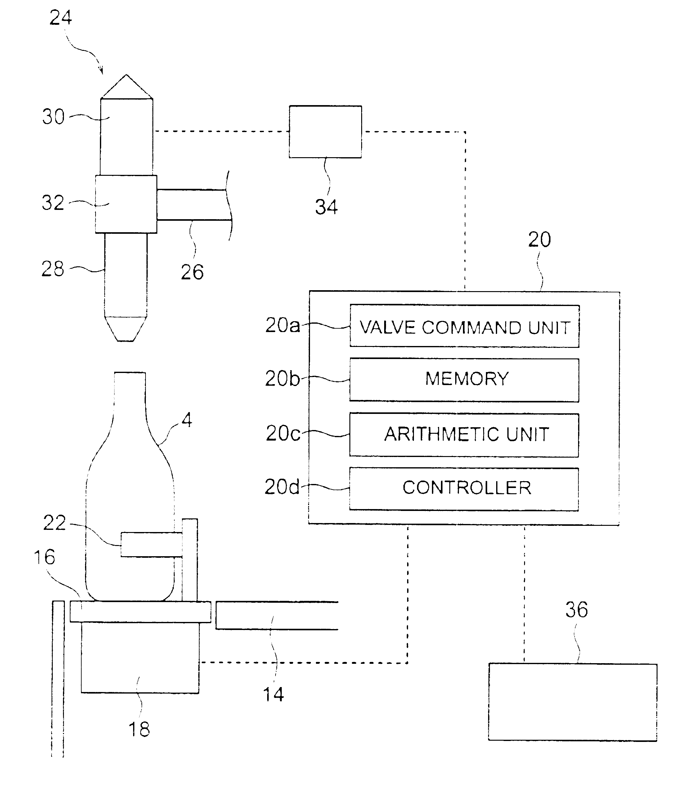
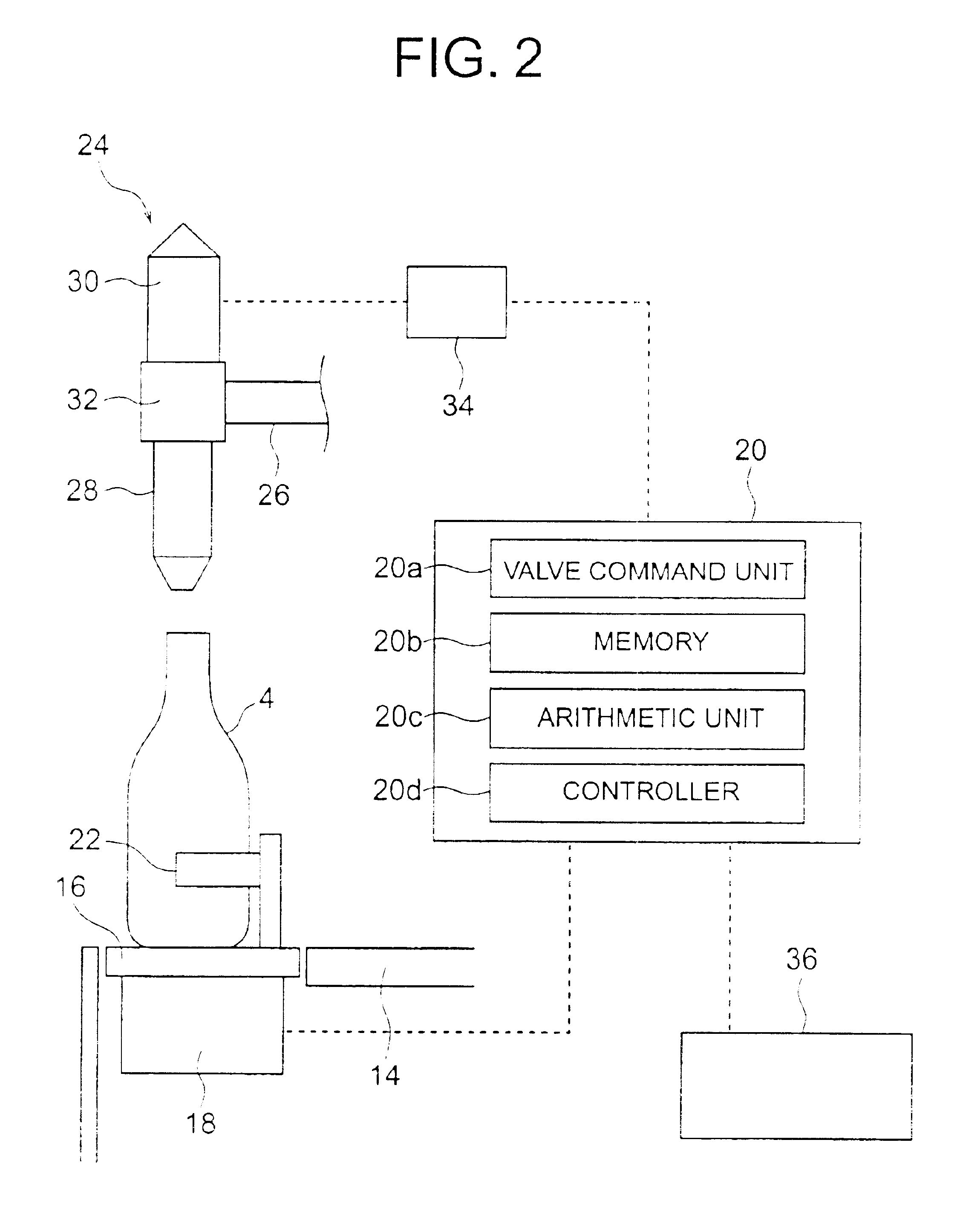
The present invention will now be described specifically with reference to an embodiment shown in the drawings. A vessel conveyor 2 conveys a vessel 4 to an inlet star wheel 6, through which the vessel is supplied into a rotary weight filler 8. The vessel 4 which is supplied into the rotary weight filler 8 is filled with a liquid while the vessel is being rotatively conveyed, and is then delivered through an outlet star wheel 10 onto a delivery conveyor 12 to be conveyed downstream.

The rotary weight filler 8 includes a revolving body 14 which rotates in a horizontal plane and which is mounted on a vertical main shaft, not shown (which is located to the right as viewed in FIG. 2), and a plurality of vessel receptacles 16 are mounted on the revolving body 14 toward the outer periphery thereof at an equal circumferential spacing. A load cell (weight measuring means) 18 is connected to each vessel receptacle 16 for measuring the weight of the vessel 4 which is placed on the vessel recep...


PUM

PropertyMeasurementUnit
rotary weightaaaaaaaaaa
frequencyaaaaaaaaaa
weight measuringaaaaaaaaaa

Abstract

A plurality of vessel receptacles and load cells are mounted along the outer periphery of a revolving body at an equal circumferential spacing. A filling device is disposed above each of the vessel receptacles. In a first operational mode for filling the receptacles, the tare of each vessel which is supplied onto one of the vessel receptacles is measured and such data is fed to a controller which determines and stores a mean value of measured tares. Subsequently, the operation is switched to a second operational mode for a filling operation. In the second operational mode, no measurement of the tare is made, and the mean value is regarded as representing the tare of supplied vessels for purposes of a filling operation. After a given time interval or after a given number of vessels have been filled, the operation is again switched to the first operational mode where the mean value is again measured. If the new mean value is different from the previous mean value, the stored mean value is rewritten. By using the stored value, the filling operation is initiated at an earlier time than when the tare is measured.

Description

BACKGROUND OF THE INVENTION AND RELATED ART STATEMENTThe present invention relates to a rotary weight filler which performs a filling operation while measuring a filled content of a vessel by weight measuring means.A rotary weight filler generally comprises a plurality of vessel receptacles disposed around the outer periphery of a revolving body at an equal circumferential spacing, a plurality of load cells (weight measuring means) mounted on the revolving body and connected to respective vessel receptacles for measuring the weight of a vessel placed on each vessel receptacle, filling means disposed above respective vessel receptacles, and control means for controlling the opening / closing of a filling valve of each filling means, and the arrangement is such that while vessels, which are placed one each on the vessel receptacle, are rotatively conveyed as the revolving body revolves, the tare of a vessel is measured by the load cell, and the filling valve is opened in response to a c...

Claims


Application Information

Patent Timeline
Patent Type & Authority Patents(United States)
IPC IPC(8): B67C3/20B67C3/02G01G17/00G01G17/06B65B3/28
CPCG01G17/06B67C3/202
Inventor NISHINO, YUKINOBUNAKADA, TATSUHIROKAKIMOTO, AKIHIKOSHIMIZU, YUTAKA
Owner SHIBUYA IND CO LTD
Why Eureka
Try Eureka