Automotive seat assembly having a self-clearing drive nut

a technology of drive nuts and assembly parts, which is applied in the direction of moving seats, machine supports, other domestic objects, etc., can solve the problems of affecting the ability of the drive mechanism to function properly, affecting the physical area under the seats of most vehicles, and proving impractical to attempt to encase or enclose the lead screw and drive nut assemblies

Inactive Publication Date: 2005-02-22
LEAR CORP
View PDF31 Cites 25 Cited by
  • Summary
  • Abstract
  • Description
  • Claims
  • Application Information

AI Technical Summary

Benefits of technology

The disadvantages of the related art are overcome by the present invention that provides an automotive seat assembly having a self-clearing drive nut. The seat assembly includes a seat frame having a main portion fixedly mounted to the bottom of a vehicle seat and a riser portion fixedly mounted to the floor pan of a vehicle. The riser portion includes a first pair of tracks and the main portion includes a cooperative second pair of tracks such that the main portion is moveably supported with respect to the riser portion along the first and second pair of tracks. A seat drive mechanism including at least one drive motor is operatively connected in driven relationship with respect to the drive motor. The lead screw has external threads defined thereon. A drive nut is also included that has a through-bore with internal threads that cooperate with the threads of the lead screw. The drive nut is adapted to cause the seat assembly to move in at least two opposed directions relative to the vehicle floor pan in response to the drive motor. Further, the drive nut also includes a second bore formed adjacent to the through-bore and extending in the general direction of the through-bore such that the internal threads of the through-bore are interrupted by the second bore. The interrupted threads of the through-bore act to clear the threads of the lead screw and cause foreign matter that collects on the lead screw to be captured by the second bore and prevented from entering the thread interface between the drive nut and the lead screw. The present invention counteracts any collection of debris on the lead screw, which causes binding and jamming of the seat drive mechanism. Thus, the present invention provides for smooth and trouble free operation of the seat assembly.

Problems solved by technology

While the seat drive mechanisms of the type generally known in the related art work well as initially installed, they are prone to certain operational complications over time that impact the drive mechanism's ability to properly function.
It has proven impractical to attempt to encase or enclose the lead screw and drive nut assemblies.
On the other hand, the physical area under the seats of most vehicles ultimately becomes cluttered and generally unclean.
In fact, the under seat area is prone to collecting dust and dirt just through normal use of a motor vehicle and also becomes a receptacle for all manner of objects.
The introduction of foreign matter to the threaded interaction of the lead screw and the drive nut may cause binding, slow and labored operation, and ultimately jamming of the seat drive mechanism.
In response to this problem, some corrective measures have been attempted in the related art with limited success.
The self-lubrication nature of these types of materials avoid having to apply a separate lubricating media to the lead screw, which reduces some collection of foreign matter on the lead screw, but does not eliminate it.
Drive nuts made of these soft and somewhat giving materials can also tolerate some amount of foreign material stuck in their threads before a binding condition occurs, but again, this does not eliminate the problem.
Both of these changes reduce the opportunity for foreign matter to enter into the threads.
However, this only slows the onset of a binding or jamming condition and does not eliminate the problem.

Method used


Image

  • Automotive seat assembly having a self-clearing drive nut
  • Automotive seat assembly having a self-clearing drive nut
  • Automotive seat assembly having a self-clearing drive nut

Examples


Embodiment Construction

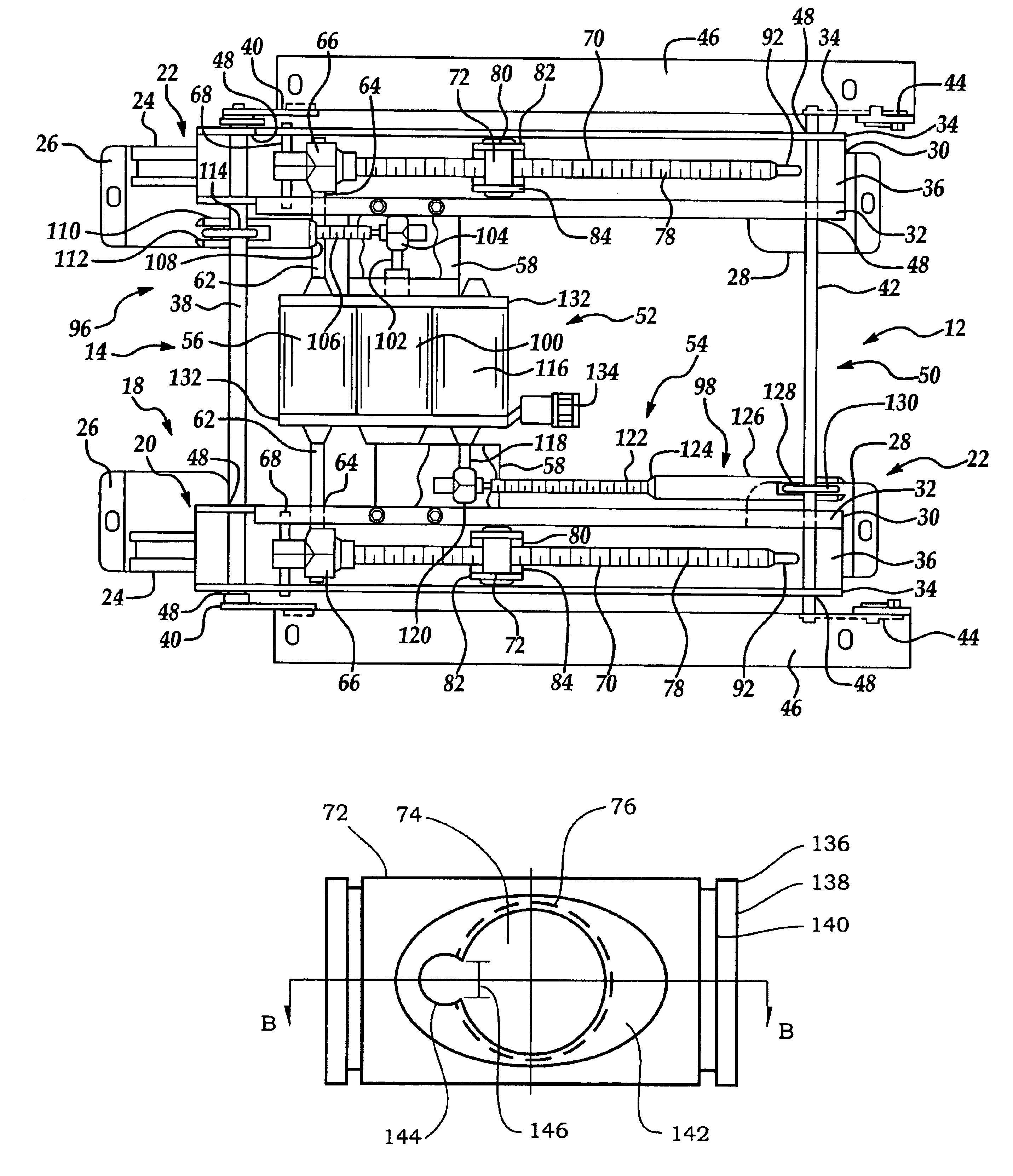
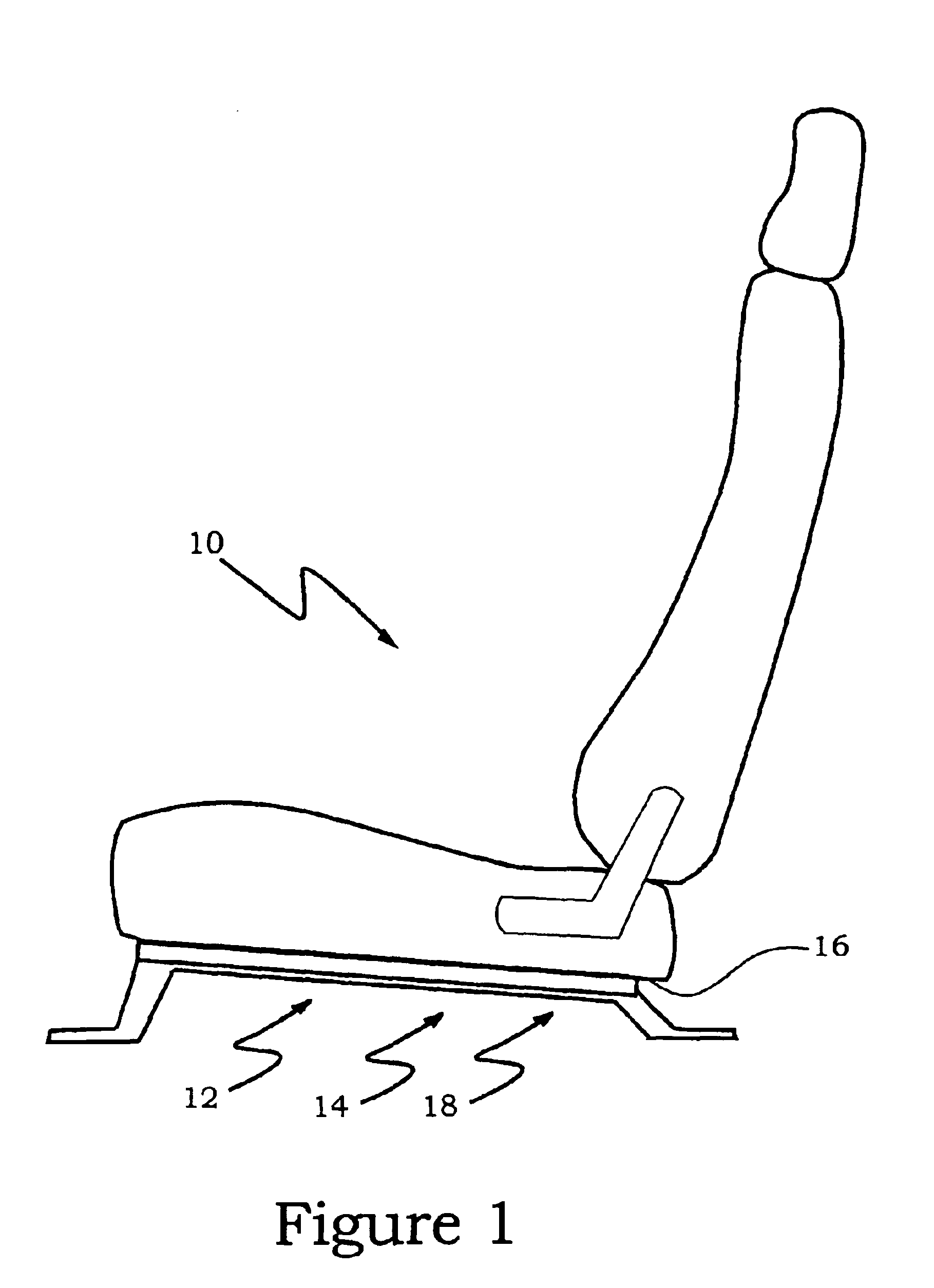
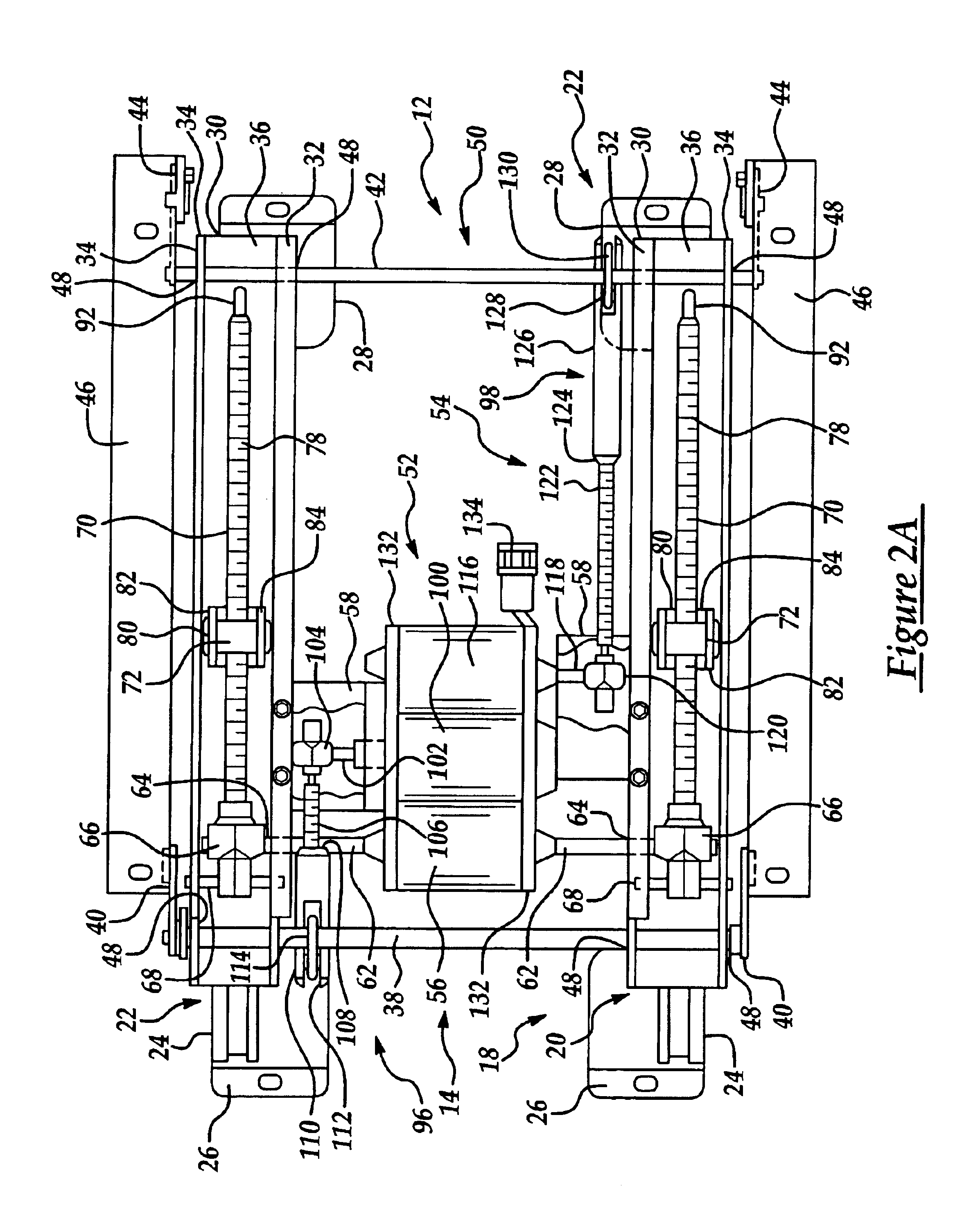
A seat assembly having a self-clearing drive nut of the present invention is generally indicated as 10 in FIG. 1 where like numerals are employed to designate like structure throughout the figures. The seat assembly 10 is power adjustable and selectively allows the operator move the seat assembly to any of a wide variety of positions. A power seat adjuster frame, generally indicated at 12, is employed to provide the motive force and physical positioning of the seat assembly 10. As shown in greater detail in FIG. 2A, the power seat adjuster frame 12 is a so-called “six-way” adjuster, which provides horizontal fore and aft, and vertical up and down movement of the front and rear ends of the seat assembly 10. By controlling the power seat adjuster frame 12, hereafter referred to simply as the seat frame, the front and rear ends of the seat assembly 10 may be moved either jointly to provide changes in elevation or separately to provide a frontward or rearward tilt of the seat. It should...


PUM


Abstract

An automotive seat assembly including a seat frame having a main portion fixedly mounted to the bottom of a vehicle seat and a riser portion fixedly mounted to the floor pan of a vehicle. A seat drive mechanism is included having at least one drive motor and a threaded lead screw. A drive nut having a through-bore with internal threads that cooperate with the threads of the lead screw is adapted to cause the seat assembly to move relative to the vehicle floor pan in response to the drive motor. The drive nut also includes a second bore formed adjacent to, and extending in the general direction of, the through-bore such that the internal threads of the through-bore are interrupted by the second bore and act to clear the threads of the lead screw and prevent foreign matter that collects on the lead screw from entering the threaded interface between the drive nut and the lead screw.

Description

BACKGROUND OF THE INVENTION1. Field of the InventionThe present invention relates, generally, to an automotive seat assembly and, more specifically, to a seat assembly that employs a self-clearing drive nut used cooperatively with a lead screw in an adjustable seat drive mechanism.2. Description of the Related ArtSeat assemblies having power seat adjusters are a popular component in many automotive vehicles. It is known to use power seat adjusters to provide powered horizontal fore and aft adjustment of the vehicle seat, as well as to use power seat adjusters to provide vertical adjustments to raise and lower the seat height. Separate front and rear seat elevation mechanisms have also been employed to independently, as well as simultaneously, adjust the elevation of the front and rear edges of a vehicle seat. Power seat recliners have also been incorporated into power seat adjusters.Typically, a vehicle power seat adjuster includes a support frame or support members that engage and ...

Claims


Application Information

Patent Timeline
Patent Type & Authority Patents(United States)
IPC IPC(8): B60N2/02B60N2/06B60N2/16
CPCB60N2/0232B60N2/0296B60N2/164B60N2/1615B60N2/067B60N2/02246
Inventor GOODBRED, NELL GENTRY
Owner LEAR CORP
Why Eureka
Try Eureka