Decorative lighting equipment

a lighting equipment and decorative technology, applied in the field of decorative lighting equipment, can solve the problems of not being suitable for a room, unable to convey a limited aesthetic feeling to the user, and creating a limited decorative effect, so as to enhance the visual effect of light appearance and achieve the effect of more effective display of decorative effects

Inactive Publication Date: 2005-02-22
KISHIMA
View PDF9 Cites 7 Cited by
  • Summary
  • Abstract
  • Description
  • Claims
  • Application Information

AI Technical Summary

Benefits of technology

When plural light-emitting diodes are placed at different points (e.g., 8 points) within the shade in a circular fashion, such a light appearance of the light flux, which can be seen as if it converges to a point when seen through the shade can be more effectively displayed.
The shade is not necessarily limited to a specific shape. However, the shade formed into a circular tube allows such a light appearance of the light flux to be more effectively displayed.
The hairlines formed on the shade may extend in a direction crossing at right angle to the direction along which the directional light flux emitted from the light source is transmitted. This directional relationship between the hairlines and the directional light flux can enhance an visual effect of the light appearance, which can be seen as if it converges to a point when seen through the shade....

Problems solved by technology

Although these types of decorative lighting equipment has been continuously modified, a conventionally applied modification is limited to coloring a light source, using a weak light source and the like, hence creating a limited decorative...

Method used


Image

  • Decorative lighting equipment
  • Decorative lighting equipment
  • Decorative lighting equipment

Examples


embodiment 1

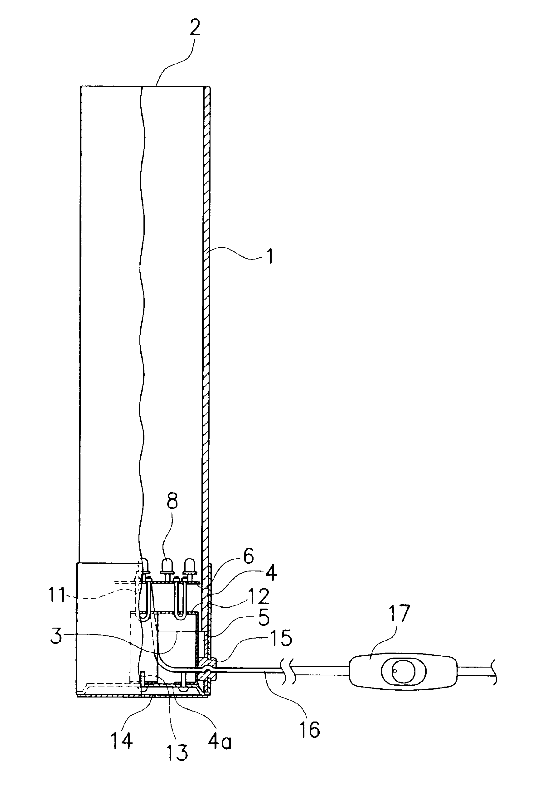
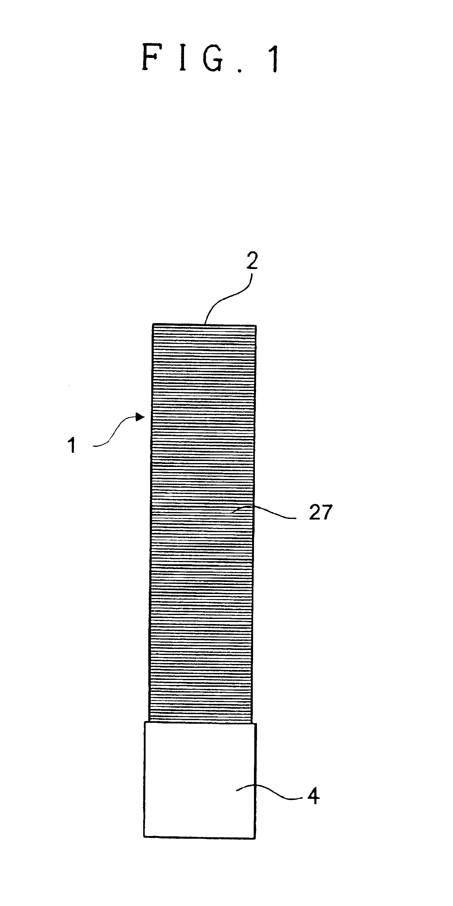
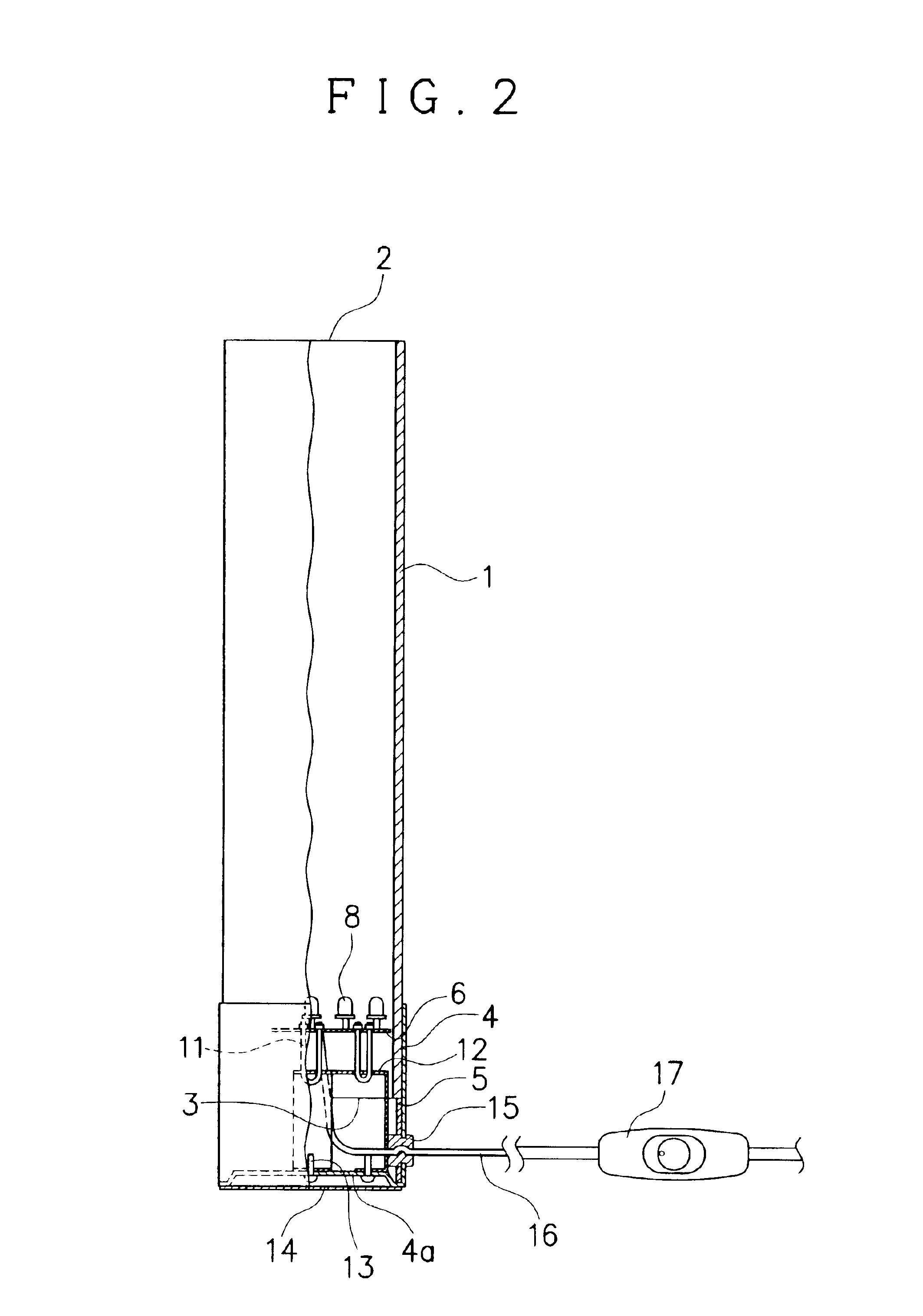
The decorative lighting equipment of this embodiment includes shade 1 fanned into a substantially circular tube, as illustrated in FIGS. 1 and 2. This shade 1 is overall transparent and made of acrylic resin. This shade 1 forms thereon a large number of hairlines 27 with thin scratch-like pattern, which extend in the circumferential direction of the shade 1, thus crossing substantially at right angle to the axial direction of the shade 1. The formation of these hairlines renders the shade 1 translucent in appearance. It is to be noted that a translucent shade can be used provided that the shade can maintain its translucency even after it is provided with the hairlines.

The shade 1 has a top end and bottom end respectively defining upper opening 2 and lower opening 3. The upper opening 2 is positioned at the top of the equipment and remains open, while the bottom end is placed in the inside of shade holding body 4 with the lower opening 3 covered by the body 4.

Placed inside of the sha...

embodiment 2

On the upper opening 2 of the shade 1 is provided decorative design applied plate 18, which projects pictorial images, geometrical patterns or any other shapes on an object surface, as illustrated in FIG. 5. Specifically, the decorative design applied plate 18 is made of a transparent acrylic resin with such pictorial images, geometrical patterns or any other shapes engraved or depicted thereon. The light fluxes emitted from the light-emitting diodes 8 pass through the decorative design applied plate 18, thereby projecting such the image on the ceiling or any other places in the room. Alternatively, a screen may be provided on the ceiling so that the image is projected thereon.

According to this embodiment, in addition to an aesthetic atmosphere created by the light appearance 26 of the light fluxes in blue, which is seen as if it converges to a point when it is seen through the shade 1, an additional aesthetic atmosphere can be created by the pictorial images, geometrical patterns o...

embodiment 3

In this embodiment, the shade 1 is provided at its upper side with upper shade 18, which radially and downwardly extends, forming a circular convex, is mounted on an upper end of shaft 19 provided along the axis of the shade 1. The upper shade 18 is made of transparent acrylic resin and has a lower surface stained in silver or any other color.

In this embodiment, the blue light fluxes emitted from the light-emitting diodes 8 converge as advancing upward, creating a unique light appearance in blue, and are reflected on the circular convex of the upper shade 18 and then dispersed to the proximity of the upper shade 18 in blurred fashion. Thus dispersed blurred light fluxes create a unique, aesthetic atmosphere in conjunction with the light appearance seen through the shade 1.

Since the shape and material of the shade 1, hairline formation, inside structure of the shade holding body 4 are the same as those of the first embodiment, the detailed description thereof are omitted.


PUM


Abstract

A decorative lighting equipment includes a shade that is transparent or translucent and formed into a tube with opposite ends, a light source for emitting a directional light flux, the light source being placed at one end of the opposite ends of the shade so that the directional light flux is transmitted within the shade toward another end of the shade, and the shade forming thereon hairlines which extend in a direction crossing the direction along which the directional light flux emitted from the light source is transmitted.

Description

BACKGROUND OF THE INVENTION1. Field of the InventionThe present invention relates to a lighting equipment and more particularly a decorative lighting equipment capable of conveying an aesthetic feeling to a user, particularly when used in a dark room with other general lighting equipment such as a fluorescent light and incandescent lamp turned off.2. Discussion of the BackgroundA main or inherent purpose of a general lighting equipment such as a room-lighting equipment and table-lighting equipment with a light source such as a fluorescent light and incandescent lamp is to light up a dark room at night or on cloudy day. On the contrary to such a general lighting equipment, some types of a lighting equipment such as an ornamental light frequently used in a restaurant, coffeehouse, bar, etc., is used to create a specific atmosphere by intentionally darkening a room by employing a weak or colored light source, or providing a stained-glass like shade.The decorative lighting equipment of ...

Claims


Application Information

Patent Timeline
IPC IPC(8): F21V1/14F21S8/00F21V1/00F21V9/10F21V9/00F21S10/02F21S10/00F21S6/00F21S2/00F21V9/40F21Y101/02
CPCF21V1/14F21S10/02F21Y2101/02F21W2121/00F21V9/10F21Y2115/10F21V9/40
Inventor KAMEDA, MASAHIROFUKUSHIMA, ATSUTOKIDA, YOSHIMITSU
Owner KISHIMA
Why Eureka
Try Eureka