Cryo-surgical apparatus and method of use

a cryo-surgical and apparatus technology, applied in the field of cryo-surgical equipment, can solve the problems of large cryo-probe size, large cryo-probe size, and large cryo-probe size, and achieve the effect of reducing the size and shape of the iceballs in the tissue, and improving the accuracy of cryo-surgical equipmen

Inactive Publication Date: 2005-02-22
ERBE ELEKTROMEDIZIN GMBH
View PDF10 Cites 125 Cited by
  • Summary
  • Abstract
  • Description
  • Claims
  • Application Information

AI Technical Summary

Benefits of technology

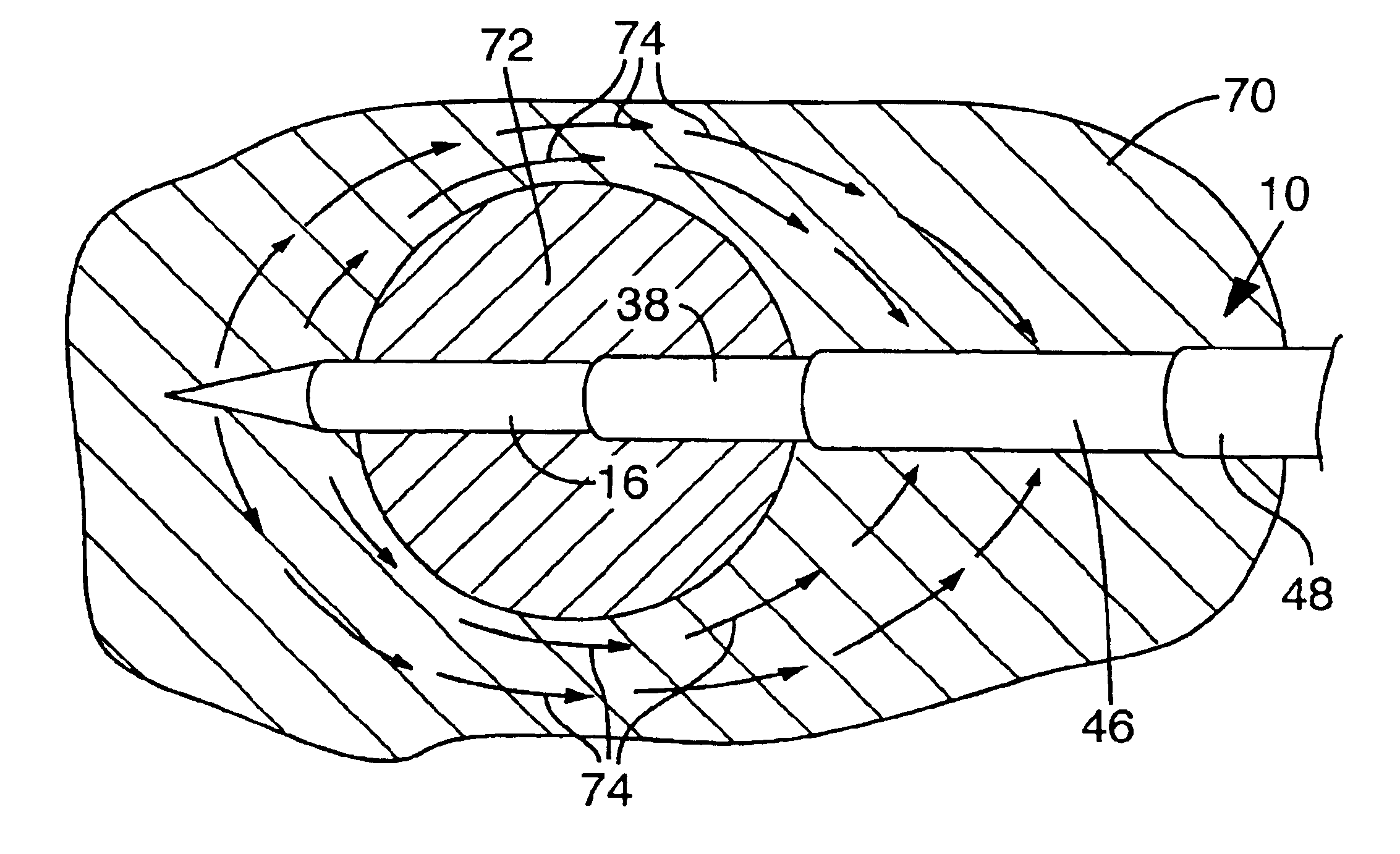
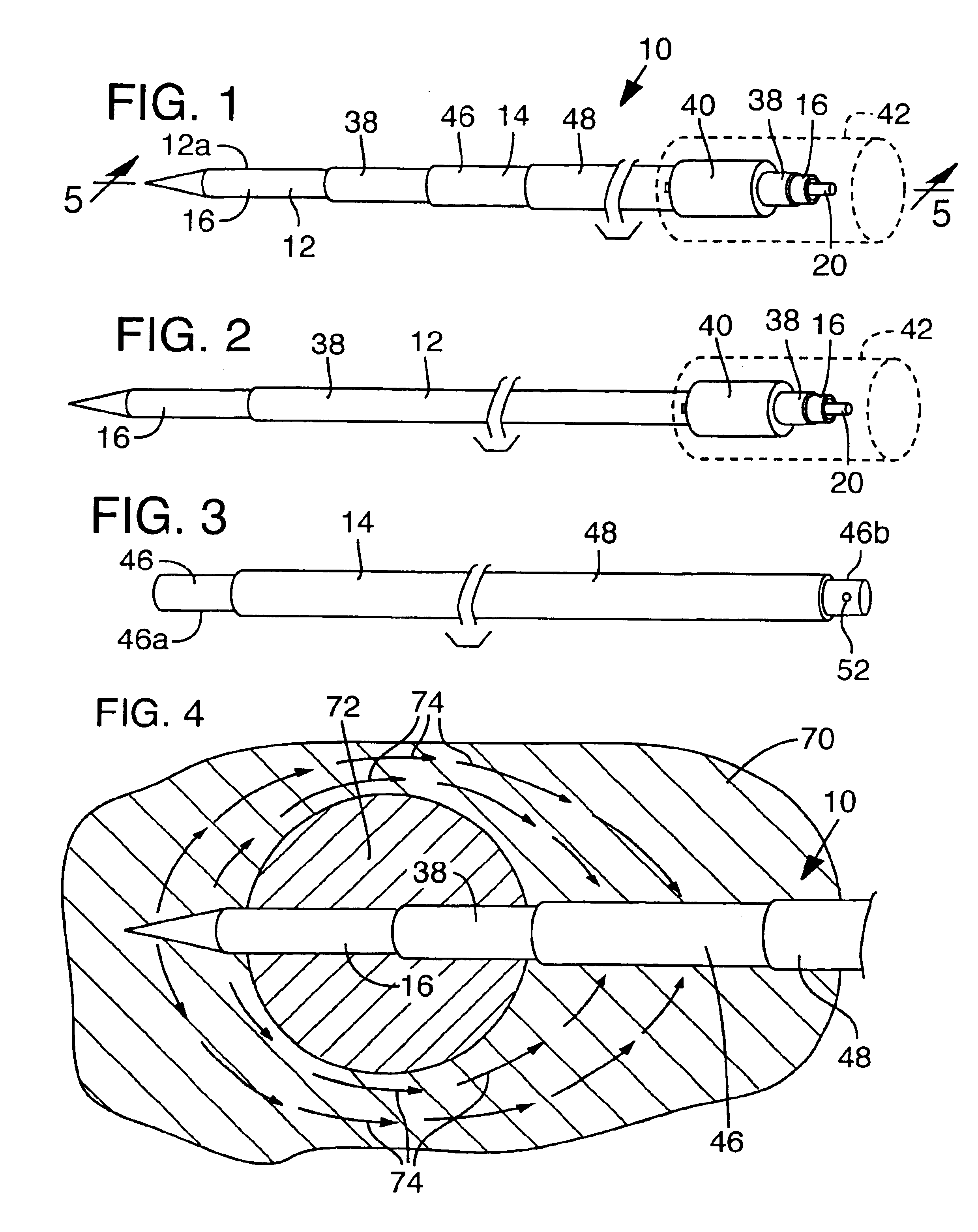
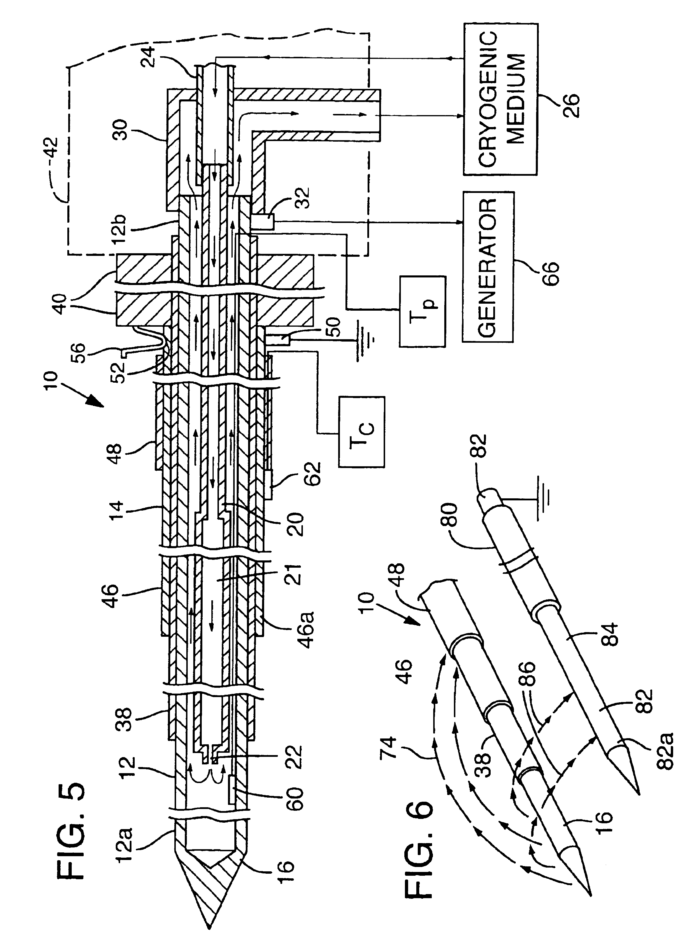
In an embodiment, the apparatus and method are such that electromagnetic energy is transmitted through the tissue surrounding the iceball formed by the cooling portion of the cryoprobe with such energy heating the adjacent and surrounding tissue to assist in controlling the configuration of the iceball.
In some embodiments, the apparatus and / or method is capable of either protecting adjacent tissue or structure from thermal damage through selective heating of surrounding tissue, or may induce additional thermal damage to surrounding tissue by means of heat producing energy transmission.

Problems solved by technology

Bleeding is often a common complication reported after the cryoablative or cryosurgical procedure.
Other limiting factors include large cryoprobe sizes, damage to the tissue directly adjacent to the cryozone or iceball, and the size and the shape of the iceballs formed in the tissue.
Additionally, cryosurgery or cryoablation of hepatic metastasis poses a different challenge.
Unlike primary hepatic tumors, for example hepatocellular carcinoma, the shapes of hepatic metastasis are irregular and typically are in poor locations whereby adjacent tissue or structure damage is a major concern.

Method used


Image

  • Cryo-surgical apparatus and method of use
  • Cryo-surgical apparatus and method of use
  • Cryo-surgical apparatus and method of use

Examples


Embodiment Construction

The singular forms “a,”“an,” and “the” refer to one or more than one, unless the context clearly dictates otherwise. For example, the term “comprising a cryoprobe” includes single or plural cryoprobe and is considered equivalent to the phrase “comprising at least one cryoprobe.”The term “or” refers to a single element of stated alternative elements or a combination of two or more elements. For example, the phrase “radiofrequency or microwave energy” refers to radiofrequency energy, microwave energy, or both radiofrequency and microwave energies.

The term “comprises” means “includes.” Thus, “comprising A and B” means “including A and B,” without excluding additional elements.

The term “proximal” refers to a portion of an instrument closer to an operator, while “distal” refers to a portion of the instrument farther away from the operator.

The term “subject” refers to both human and animal subjects. In certain embodiments, the subject is a human or other mammal.

Referring to the drawings, ...


PUM


Abstract

Cryosurgical apparatus includes an elongate cryoprobe having a cooling portion and an electrically conductive first portion in the region of the cooling portion. A removable sheath having an electrically conductive second portion is received on the cryoprobe with its electrically conductive second portion spaced from the electrically conductive first portion of the cryoprobe. Electrical insulation is interposed between the first portion and the second portion. Coolant material supplied to the cryoprobe produces tissue freezing in the region of the cooling portion. Electromagnetic energy supplied to either the first portion or the second portion, while the other of such first portion or second portion is connected to ground, provides selective heating in tissue surrounding an iceball produced by the cooling portion to control the configuration of the iceball.

Description

FIELDThis invention relates to cryoprobe apparatus for use in cryosurgery and other applications. More specifically it relates to a cryo-surgical apparatus having the enhanced ability to control the configuration of iceballs formed in tissue.BACKGROUNDCryosurgery, or cryoablation, is one of the oldest of the local thermal ablation techniques. It was initially developed in the 19th century. It has been used for destroying and controlling tissue, such as tumors, deep within the body.The use of cryosurgical probes for cryosurgery, or cryoablation, has been described in many clinical reports for the treatment of a variety of different benign and malignant tumors. In addition the use of the cryosurgical probes for cryosurgery, or cryoablation, has been described in laparscopic and percutaneous clinical reports.A summary of the general history of cryosurgery and the mechanism involved therein is well set out in an article entitled “Cryosurgery,” by Boris Rubinsky published in the Annual R...

Claims


Application Information

Patent Timeline
Patent Type & Authority Patents(United States)
IPC IPC(8): A61B18/02A61B18/00A61B18/14A61B18/18
CPCA61B18/02A61B18/1477A61B2018/1425A61B2018/0262
Inventor MAURICE, GEORGE T.
Owner ERBE ELEKTROMEDIZIN GMBH
Why Eureka
Try Eureka