Switching power converter and control system

a power converter and control system technology, applied in the field of electrical devices, can solve the problems that the power factor correction cannot be provided using these topologies, and achieve the effect of controlling the conductivity of the switch

Active Publication Date: 2011-12-13
CIRRUS LOGIC INC
View PDF264 Cites 117 Cited by
  • Summary
  • Abstract
  • Description
  • Claims
  • Application Information

AI Technical Summary

Benefits of technology

[0016]In one embodiment of the present invention, an apparatus includes a switching power converter. The switching power converter includes an input stage. The input stage includes an input node to receive a time-varying input signal and a first inductor coupled to the input node. The switching power converter also includes an output stage coupled to the input stage. The output stage includes a capacitor and a second inductor coupled to the capacitor. the switching power converter also includes a switch, coupled to the input stage and the output stage, to control energy transfer to the capacitor. The apparatus also includes a switch state controller, coupled to the switch, to monitor the time-varying input signal and to supply a switching power converter control signal to the switch to modulate a switching frequency of the switch in accordance with amplitude changes of the input signal. The switching frequency of the switch is greater than a frequency of the input signal.
[0017]In another embodiment of the present invention, a method includes generating a pulse width modulated switching power converter control signal and monitoring a time-varying input signal to the switching power converter. The method also includes monitoring a boost capacitor voltage of the switching power converter and

Problems solved by technology

However, power factor correction generally

Method used


Image

  • Switching power converter and control system
  • Switching power converter and control system
  • Switching power converter and control system

Examples


Embodiment Construction

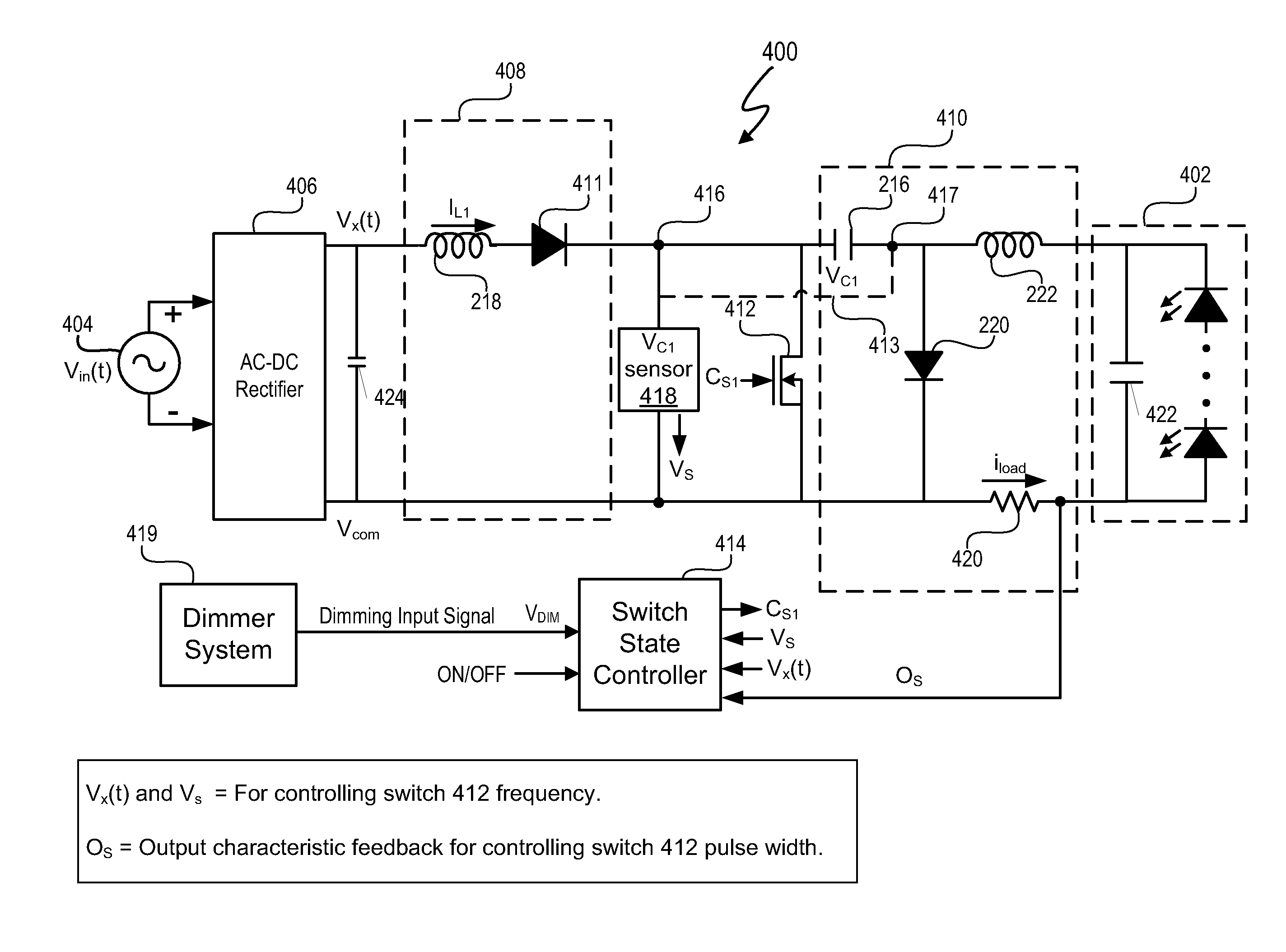
[0027]A switching power converter tracks a time-varying input voltage during each cycle of the input voltage to provide power factor correction. The switching power converter includes a switch with a frequency and duty cycle modulated control signal. The switch controls the transfer of energy between the input and output of the switching power converter. The frequency of the control signal is greater than a frequency of the input signal. The control signal frequency is modulated during each cycle of the input voltage so that energy transferred from the switching power converter tracks the energy supplied to the switching power converter. In at least one embodiment, the switching power converter has no theoretical limits to driving total harmonic distortion (THD) to 0 and obtaining a power factor correction (PFC) of one for a modulation index (MI) greater than one. Circuit component imperfections and other actual non-idealities prevent switching power converter from actually achievin...


PUM


Abstract

A switching power converter tracks a time-varying input voltage during each cycle of the input voltage to provide power factor correction. The switching power converter includes a switch with a frequency and duty cycle modulated control signal. The switch controls the transfer of energy between the input and output of the switching power converter. The frequency of the control signal is greater than a frequency of the input signal. The control signal frequency is modulated during each cycle of the input voltage so that energy transferred from the switching power tracks the energy supplied to the switching power converter.

Description

CROSS-REFERENCE TO RELATED APPLICATION[0001]This application also claims the benefit under 35 U.S.C. §119(e) and 37 C.F.R. §1.78 of U.S. Provisional Application No. 60 / 894,295, filed Mar. 12, 2007 and entitled “Lighting Fixture”. U.S. Provisional Application No. 60 / 894,295 includes exemplary systems and methods and is incorporated by reference in its entirety.[0002]This application claims the benefit under 35 U.S.C. §119(e) and 37 C.F.R. §1.78 of U.S. Provisional Application No. 60 / 915,547, filed May 2, 2007, and entitled “Power Factor Correction (PFC) Controller Apparatuses and Methods,” and is incorporated by reference in its entirety.BACKGROUND OF THE INVENTION[0003]1. Field of the Invention[0004]The present invention relates in general to the field of electronics, and more specifically to a switching power converter and control system.[0005]2. Description of the Related Art[0006]Power converters convert one source of input power into another source of power. For example, power c...

Claims


Application Information

Patent Timeline
IPC IPC(8): G05F5/00H05B41/16
CPCH02M1/4208H02M3/005H05B33/0815H02M2001/0022Y02B20/346Y02B70/126H05B45/3725H02M1/0022Y02B20/30Y02B70/10
Inventor MELANSON, JOHN L.
Owner CIRRUS LOGIC INC
Why Eureka
Try Eureka