Flush-mounted antenna and transmission system

a transmission system and flush technology, applied in the direction of antennas, slot antennas, antennas, etc., can solve the problems of limiting the area the antenna can occupy, limiting/or receive signals through the antenna, etc., to reduce the total efficiency of the device during transmission and/or reception, and limit the ability of the device to transmit.

Inactive Publication Date: 2005-02-22
SILVER SPRING NETWORKS
View PDF9 Cites 125 Cited by
  • Summary
  • Abstract
  • Description
  • Claims
  • Application Information

AI Technical Summary

Benefits of technology

In some applications, however, it is desirable that the antenna not extend outward from the surface, but rather be mounted flush with the surface. Often, mounting the antenna flush with the surface limits the area the antenna can occupy. Furthermore, mounting the antenna flush with the surface may limit the ability of the device to transmit and / or receive signals through the antenna. It therefore becomes desirable, in these applications, to provide a matching network for the device that will not significantly reduce the total efficiency of the device during transmission and / or reception and that can be configured in a small, compact construction.

Problems solved by technology

Often, mounting the antenna flush with the surface limits the area the antenna can occupy.
Furthermore, mounting the antenna flush with the surface may limit the ability of the device to transmit and / or receive signals through the antenna.

Method used


Image

  • Flush-mounted antenna and transmission system
  • Flush-mounted antenna and transmission system
  • Flush-mounted antenna and transmission system

Examples


first embodiment

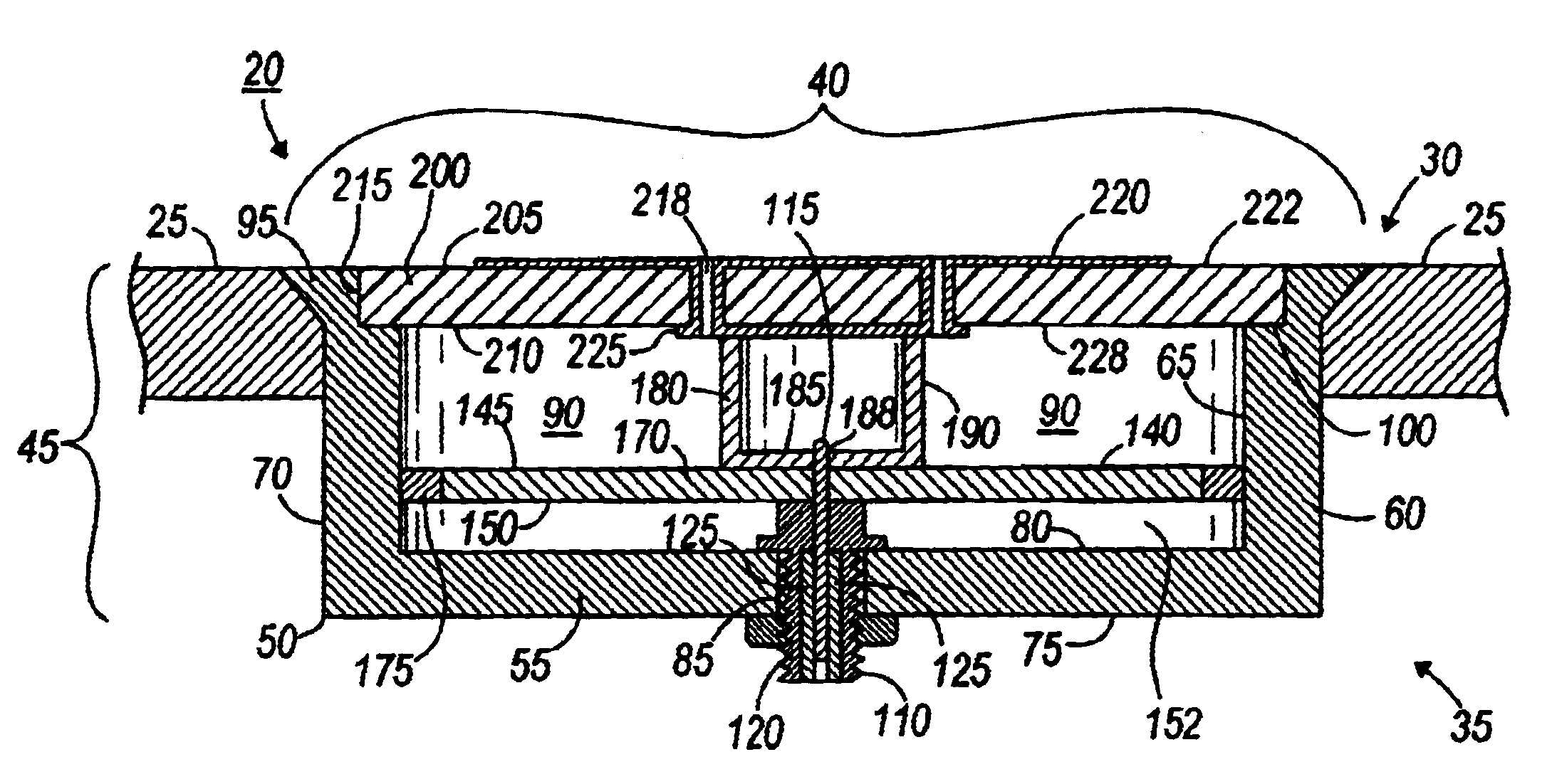
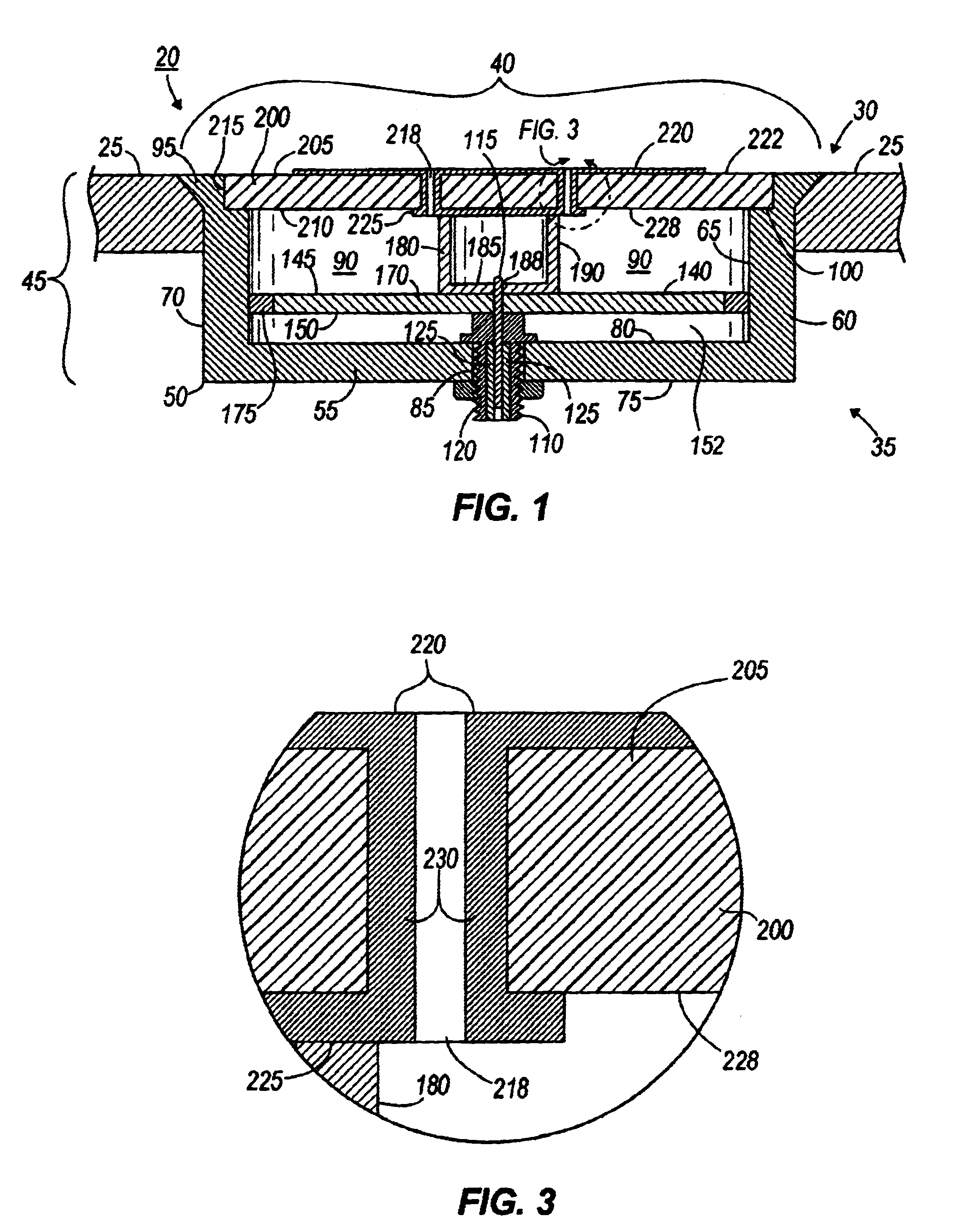
an apparatus 20 in accordance with the present invention is shown in FIGS. 1-3 and illustrated schematically in FIGS. 6 and 7. The apparatus 20 is configured to be positioned substantially beneath a surface 25 as shown in FIG. 1. In some constructions, the surface 25 is an outer surface of a housing or enclosure that defines a cavity into which a communication device, such as, for example, a transmitter, a receiver and / or a transceiver (all not shown), is positioned. In some constructions, the surface 25 is included in a support structure or is a portion of a street, sidewalk or ground.

The apparatus 20 includes a top portion 30 which is positioned substantially flush with the surface 25 and a bottom portion 35 which is positioned substantially beneath the surface 25. The top portion 30 includes an antenna 40, which will be discussed below. The bottom portion 35 includes a matching network 45 to couple the antenna 40 to the communication device. In some constructions, the matching ne...


PUM


Abstract

An apparatus mounted beneath or behind a surface and being operable to transmit or receive wireless communication signals for transmitting information from one location to a remote location. The apparatus includes an antenna mounted substantially flush with a surface. The apparatus also includes a communication device and a matching network having a radial transmission line. The communication device is connected to the antenna via the matching network and includes either a transmitter, a receiver or a transceiver.

Description

BACKGROUND OF THE INVENTIONThe present invention relates generally to antennas for effecting wireless communication from an electronic device, and particularly, to a flush-mounted antenna for the device.There are many applications in which it is desired to obtain information from a electronic device via wireless communication. Often, the device is located beneath a surface of a supporting structure, integrated into a surface of a supporting structure and / or positioned within a housing or enclosure having an outer surface. In order to effect wireless communication, the communication signal much somehow be transmitted through the surface. In the usual case, this is done by inserting an antenna through a hole in the surface.SUMMARY OF THE INVENTIONIn some applications, however, it is desirable that the antenna not extend outward from the surface, but rather be mounted flush with the surface. Often, mounting the antenna flush with the surface limits the area the antenna can occupy. Furt...

Claims


Application Information

Patent Timeline
Patent Type & Authority Patents(United States)
IPC IPC(8): H01Q1/27H01Q1/28H01Q13/10H01Q13/18
CPCH01Q1/286H01Q13/18H01Q13/10
Inventor LIZALEK, GARY C.LUGLIO, JUAN R.
Owner SILVER SPRING NETWORKS
Why Eureka
Try Eureka