Connector clip for verifying complete connection

a technology of connecting pins and connectors, applied in the direction of hose connections, couplings, bends, etc., can solve the problems of internal fluid leakage, lowering sealing properties, and affecting the fitting of the connectors

Inactive Publication Date: 2005-03-01
SUMITOMO RIKO CO LTD
View PDF16 Cites 15 Cited by
  • Summary
  • Abstract
  • Description
  • Claims
  • Application Information

AI Technical Summary

Benefits of technology

Accordingly, it is an object of the present invention to provide a connector clip not only having a checking function to easily verify that a pipe is fully inserted and fitted in a connector, but also having a lock function precisely preventing relative rotational movement of the connector with respect to the pipe
The connector connecting portion of the connector clip engages with the tube connecting portion of the connector or with the tube connected to the tube connecting portion , so that the connector clip moves rotationally along with the connector when, or provided that the connector is rotationally moved . And also, the pipe connecting portion receives the pipe, so that the connector clip moves rotationally along with the pipe when, or provided that the pipe is rotationally moved. That is, the pipe is connected to the connector via the connector clip not to move rotationally relatively with respect to the connector. In the present invention, the pipe includes the straight pipe portion, and the curved portion disposed or formed on an opposite axial end of the straight pipe portion. The pipe connecting portion of the connector clip receives the curved portion or a portion of the pipe extending from the curved portion in co-rotatable relation. Thus configured structure of receiving the curved portion of the pipe in the pipe connecting portion enables to simplify a shape or a configuration of the connector clip with lock function against rotation and to construct the connector clip which can be easily connected to the pipe.
However, as in the case above, the pipe may not be fitted in the straight pipe portion slot smoothly, or the connector clip may not be easily mounted onto the connector. Especially, if a connector clip having a number of fit-engagement portions, or a wide range of fit-engagement portions are made of a fiber reinforced resin material, a working efficiency for mounting of the connector clip will be considerably lowered. Therefore, it is effective to provide integrally one or a plurality of reinforcing ribs extending in a circumferential direction around an outer surface of the straight pipe receiving portion, in order to enhance resistance to widening deformation or movement of the straight pipe portion slot. For example, a plurality of reinforcing ribs are disposed in longitudinally spaced relation each other. This configuration provides sufficient resistance to widening deformation or movement to block the annular projection of the pipe against fitting in the straight pipe portion slot of the straight pipe receiving portion with thin-wall, or relatively thin-wall configuration, and a favorable or relatively favorable working efficiency for mounting of the connector clip. In order to enhance reinforcing effectiveness of the reinforcing rib, a protruding or projecting portion such as a frame portion or an edge portion is formed so as to protrude or project laterally outwardly at an opening of the straight pipe portion slot, and the reinforcing rib is formed so as to extend from one end of the projecting portion to an opposite end of the projecting portion.
A piping connecting structure is constructed by a connector, a tube connected to a tube connecting portion of the connector, a pipe inserted and fitted in a pipe inserting portion of the connector and a connector clip. A connector clip of the present invention has not only a function to prevent incomplete connection or a half-fitting between a connector and a pipe, but also a function to restrain relative rotation of the connector and the pipe. Thus, the connector clip of the present invention serves to effectively prevent such inconveniences that a piping system is under operation wherein the pipe has not been connected with the connector completely, and that sealing property between the connector and the pipe is deteriorated as a sealing member is worn. And the connector clip of the present invention can be integrally molded as a single unit, and can be easily mounted onto the connector and the pipe. This results in cost saving for piping.

Problems solved by technology

If an operator does not take care sufficiently to complete connection between the pipe and the connector, the pipe might not be fully inserted into the retainer and the annular engagement projection of the pipe might not snap-engage with one axial end portion of the retainer, or the retainer might not be fitted properly in the pipe inserting portion of the connector.
However, in case of a piping system subject to operation while the pipe is incompletely connected to the connector, usually sealing property by the sealing member between the connector and the pipe becomes lowered, and an internal fluid leaks out.
Further, for example, in case that a resin tube connected to a connector leads to a gasoline engine of a vehicle, as the connector constantly moves rotationally at a small angle relative to a pipe by vibration transmitted from the gasoline engine via the resin tube to the connector, a sealing member or members disposed between the connector and the pipe becomes thereby worn, and thus sealing property is lowered therebetween.
However, if the bracket G is formed short, a vehicle mechanical layout often does not allow the opposite end portion H thereof to reach and fix to a vehicle body.
As this restraint member is, however, configured to clip the outer peripheral surface of the connector, it is difficult to use the restraint member along with a clip for verifying complete connection or fitting between the pipe and the connector.
That bothers the operator.

Method used


Image

  • Connector clip for verifying complete connection
  • Connector clip for verifying complete connection
  • Connector clip for verifying complete connection

Examples


Embodiment Construction

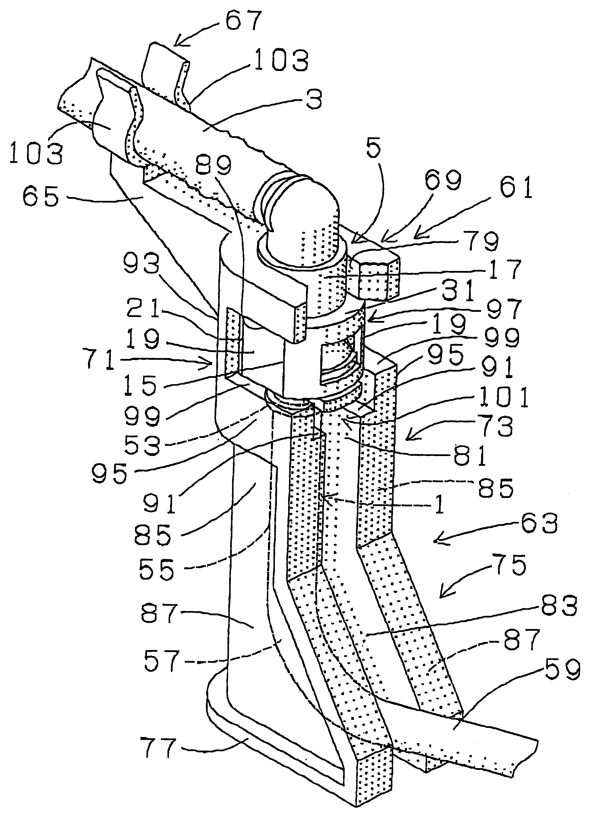
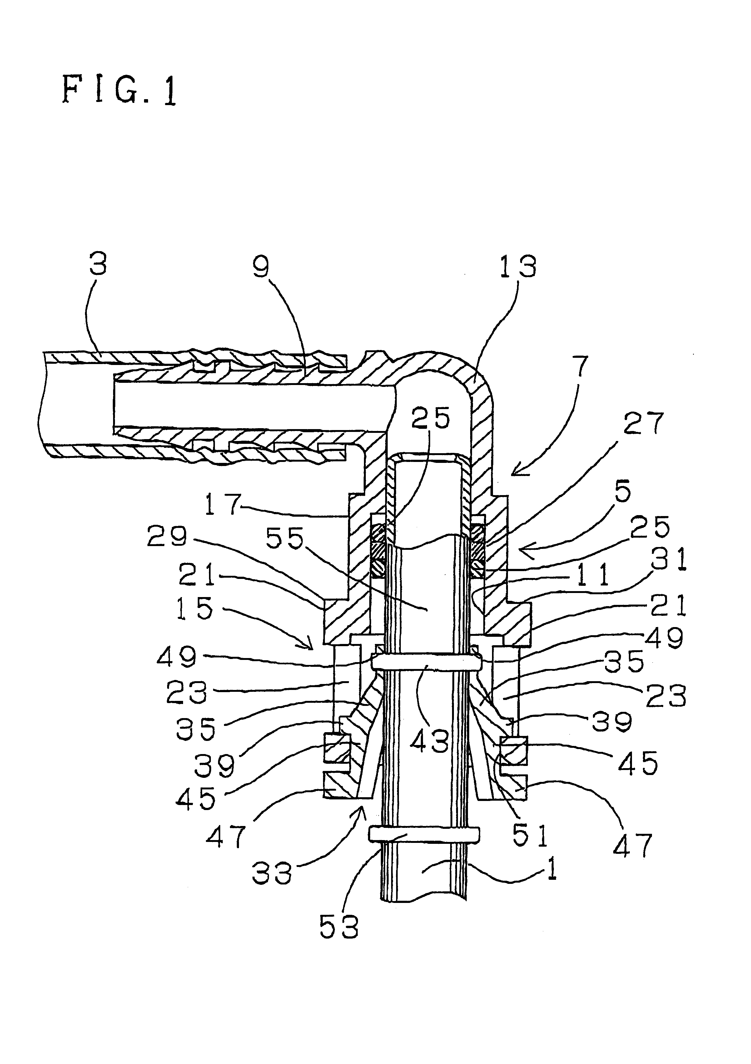
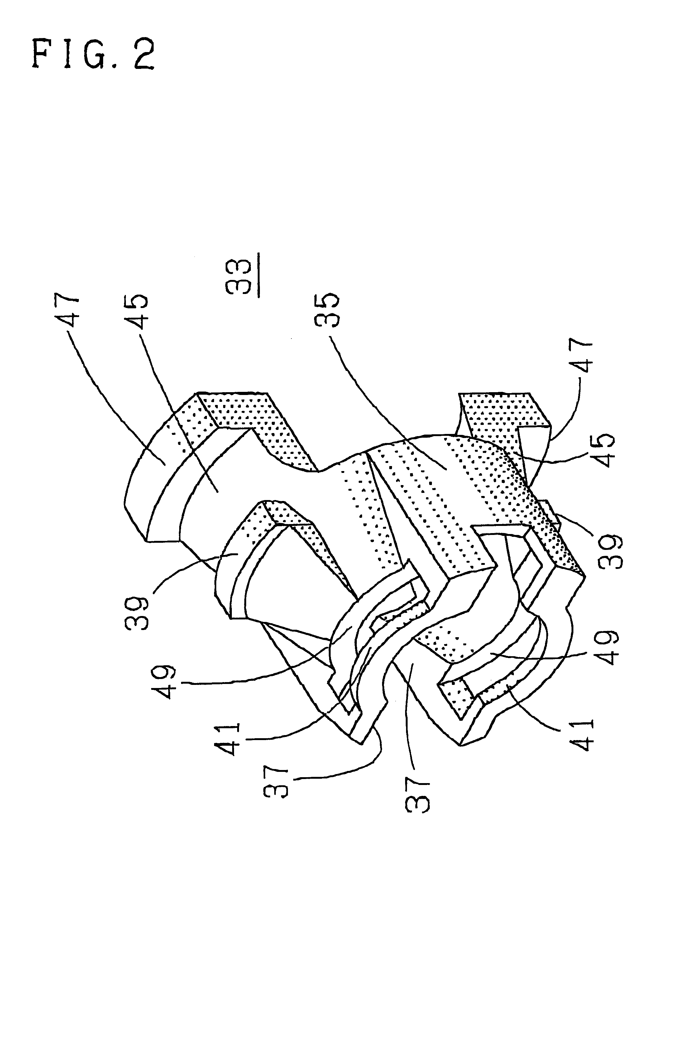
As shown in FIG. 1, a gasoline fuel piping for vehicle is constructed by connecting a metallic pipe 1 with a resin tube 3. A connector 5 made of glass fiber reinforced polyamide (PA / GF) is applied to construct a connecting portion between the pipe 1 and the resin tube 3 in the piping, wherein the resin tube 3 is fittingly connected to the connector 5 on one axial end thereof, and then the pipe 1 is fittingly inserted into an opposite axial end of the connector 5. The connector 5 comprises a pipe inserting portion 7, and a resin tube connecting portion 9 which is formed integrally on one axial end portion of the pipe inserting portion 7 in connected state. The resin tube connecting portion 9 is extending in a curved manner (in a curved manner at right angle in this embodiment) from one axial end portion of the pipe inserting portion 7 or is disposed at an angle (at 90° or transversely in this embodiment) with respect to the pipe inserting portion 7, and a bore 11 is provided in the c...


PUM


Abstract

A connector clip integrally comprises a holder portion and a C-shaped clamp on one longitudinal end portion of the holder portion. The holder portion is mounted to a length from a connector to a curved portion of a pipe. The C-shaped clamp clips a tube connected to a tube connecting portion of the connector. The holder portion comprises a holding portion to hold a length from a tubular holder portion of the connector to an annular projection of the pipe therein, a first receiving portion formed on an opposite longitudinal side from the holding portion to receive a straight pipe portion of the pipe, and a second receiving portion formed on an opposite longitudinal side from the first receiving portion to receive a curved portion of the pipe.

Description

BACKGROUND OF THE INVENTIONThe present invention relates to a connector clip adapted to verify that a complete connection has been made between a connector used in a connecting portion of a piping such as a fuel piping of a vehicle, and a pipe inserted into the connector, or adapted to prevent an incomplete fitting or connection therebetween.In a fluid piping structure where a pipe is connected to a tube, a connector is used for connecting the pipe to the tube. In such piping system, for example, the pipe is formed with an annular engagement projection on one axial end of an outer peripheral surface thereof, and the connector is configured with a retainer to be fitted in a pipe inserting portion thereof. Then, the pipe is inserted into the retainer so that the annular engagement projection snap-engages with one axial end portion of the retainer providing a stop mechanism that prevents the pipe from coming off the connector, and consequently, the pipe is completely connected to the c...

Claims


Application Information

Patent Timeline
Patent Type & Authority Patents(United States)
IPC IPC(8): F16L3/13F16L3/12F02M37/00F16L3/02
CPCF16L3/1226F16L3/13F16L37/0987Y10S285/921F16L2201/10
Inventor INOUE, TOMOKI
Owner SUMITOMO RIKO CO LTD
Why Eureka
Try Eureka