Connector and method of mounting a connector housing on a panel

a technology of connector housing and connector housing, which is applied in the direction of electrical equipment, substation/switching arrangement details, coupling device connections, etc., can solve the problems ofb>1/b> partly mounting

Inactive Publication Date: 2005-03-01
SUMITOMO WIRING SYST LTD
View PDF15 Cites 15 Cited by
  • Summary
  • Abstract
  • Description
  • Claims
  • Application Information

AI Technical Summary

Benefits of technology

The invention is directed to a connector that can be passed through and mounted to a mount hole in a panel. The invention comprises a holding means for holding the housing on th

Problems solved by technology

For example, the housing 1 may not be fixed firmly to the panel P at an intermediate stage

Method used


Image

  • Connector and method of mounting a connector housing on a panel
  • Connector and method of mounting a connector housing on a panel
  • Connector and method of mounting a connector housing on a panel

Examples


first embodiment

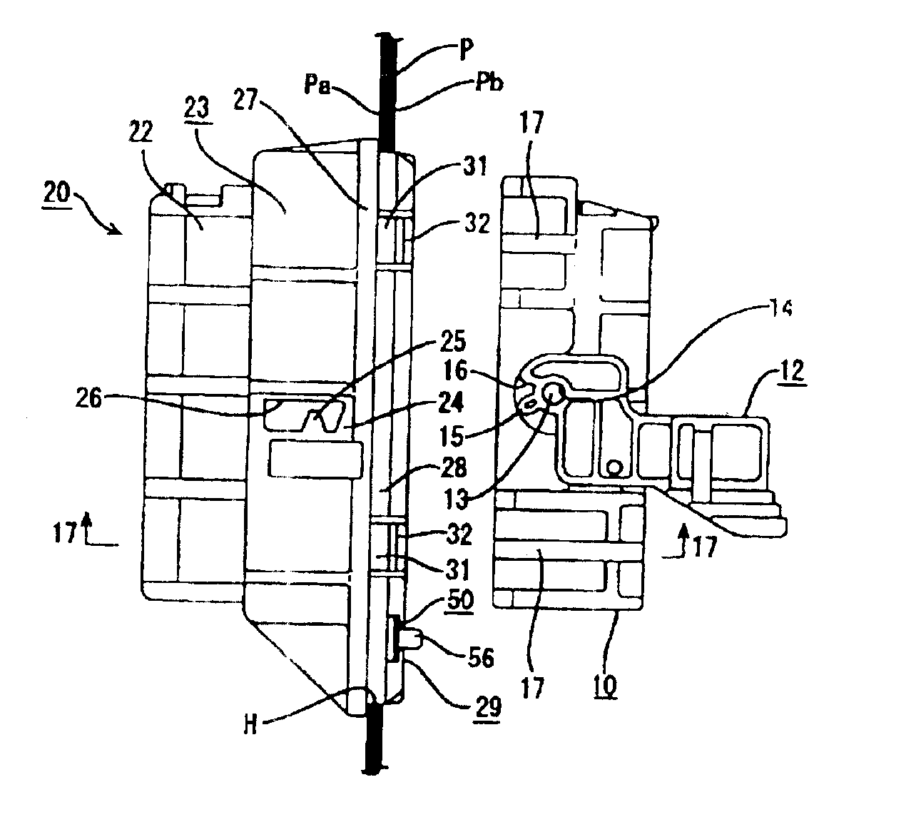
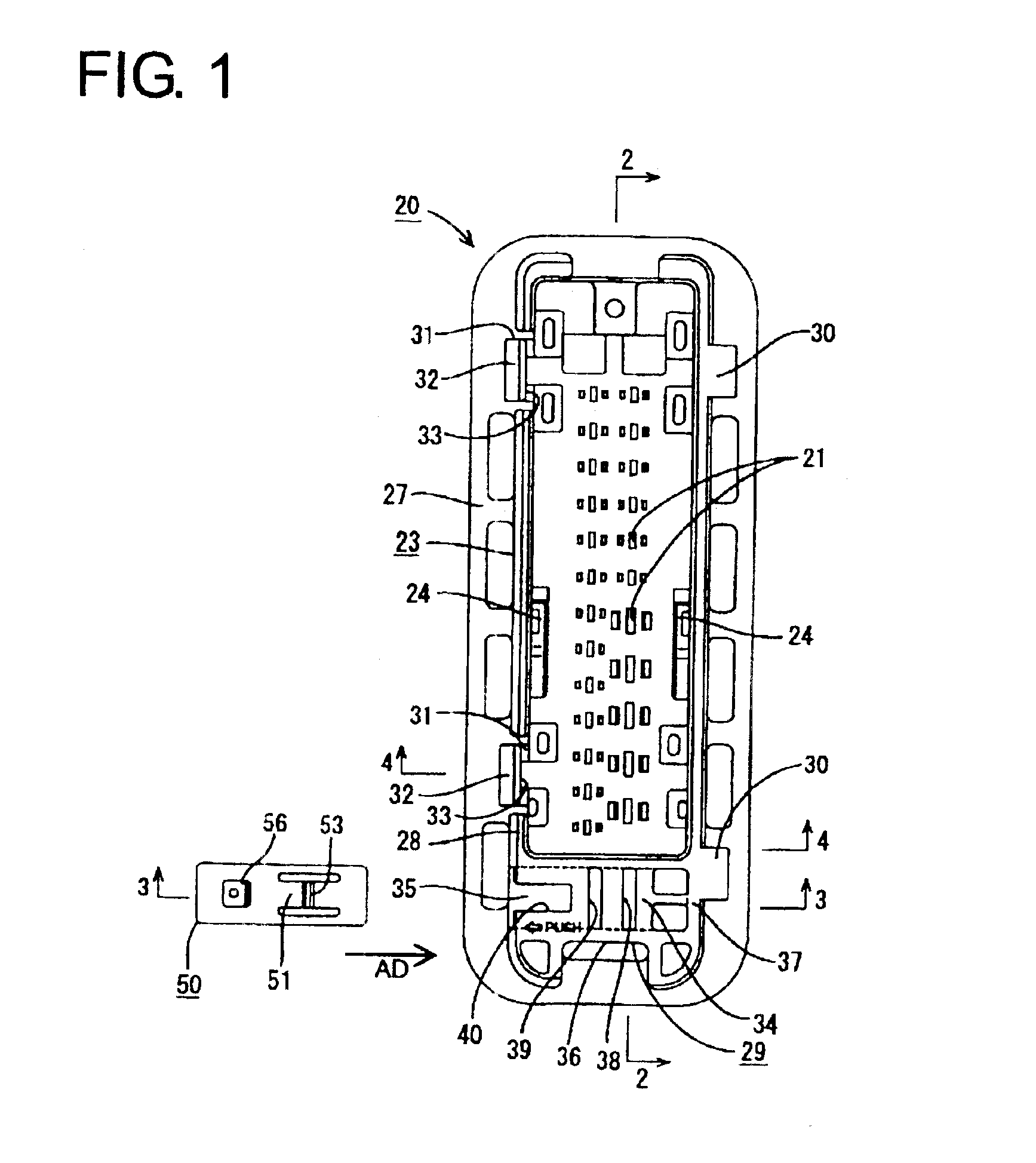
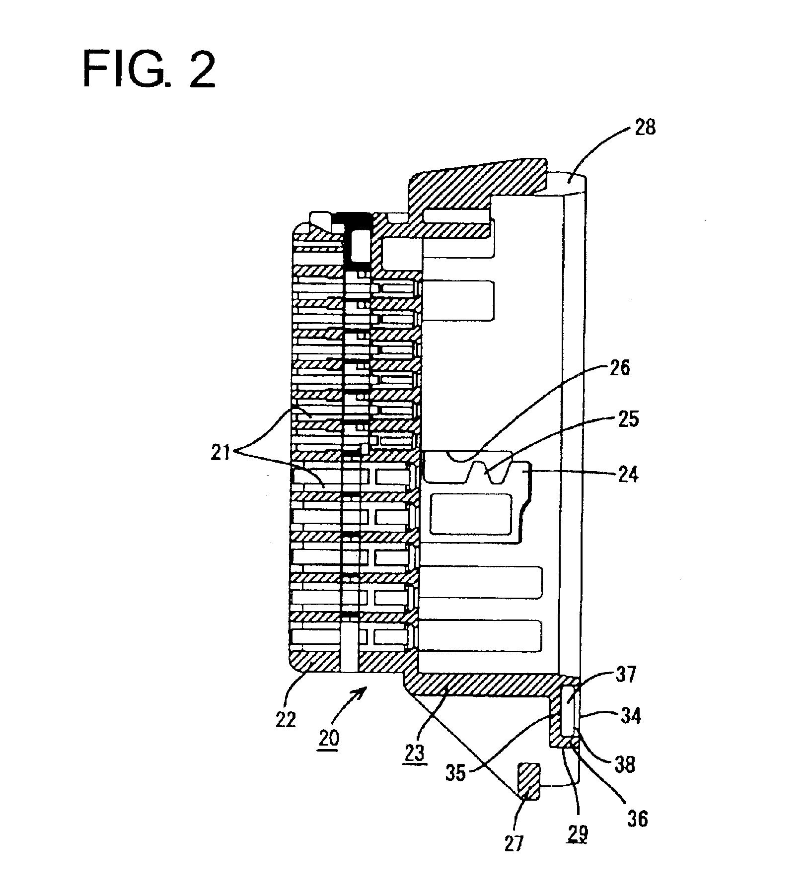
a connector according to the invention is intended for mounting on a door panel of an automotive vehicle and is described with reference to FIGS. 1 to 23. This connector has a male housing 20 that can be mounted to a mount hole H in a panel P by inserting the housing 20 into the mount hole H from the rear side of the panel P. The connector also has a female housing 10 that is connectable with the male housing 20 from the front side of the panel P. The mounting direction of the male housing 20 onto the panel P is referred to as the forward direction in the following description.

The female housing 10 is made e.g. of a synthetic resin and, as shown in FIGS. 15 and 16, is substantially a block with cavities 11 for accommodating unillustrated female terminal fittings. The connector further has a U-shaped lever 12 and shaft pins 13 that project from the longer outer surfaces of the female housing 10. The shaft pins 13 pass through shaft holes 14 in the lever 12 so that the lever 12 can ro...

second embodiment

the invention is described with reference to FIGS. 24 to 36. Identical or similar elements and features as in the previous embodiment are denoted with the same reference numerals so that a repetitive description thereof is omitted hereinafter.

As shown in FIGS. 24 and 26, a resiliently deformable locking piece 57 is cantilevered from an end of the detector 50 substantially opposite from the detecting portion 54. The locking piece 57 is about half the width and thickness of the detector 50 and is at the front side of the detector 50 with respect to the accommodating direction AD in FIG. 24. A hook-shaped locking claw 58 is formed at the rear surface of the leading end of the locking piece 57 and projects back in a direction substantially opposite to the mounting direction MD. A front half of the stop wall 37 of the detector accommodating portion 29 is cut away to define an insertion hole 41 that permits insertion of the locking piece 57, as shown in FIG. 24. The rear wall 35 of the de...


PUM


Abstract

A housing (20) of a connector has a front end that can be introduced through a mount hole (H) in a panel (P). A detector (50) is mounted on the front end of the housing (20) is movable between a standby position and a detecting position. Movement of the detector (50) toward the detecting position is prevented by interference with the inner peripheral surface of the mount hole (H) while the housing (20) is being mounted on the panel (P). However, the inner peripheral surface of the mount hole (H) when the male housing (20) is mounted properly on the panel (P). Thus, the detector (50) can be moved to the detecting position.

Description

BACKGROUND OF THE INVENTION1. Field of the InventionThe invention relates to a connector mountable on a panel and to a method of mounting a connector housing of a connector on a panel.2. Description of the Related ArtU.S. Pat. No. 5,779,500 and FIG. 37 herein show a connector that is mountable on a door panel of an automotive vehicle. With reference to FIG. 37, the connector has a housing 1 that can pass through a mount hole H in a panel P. The housing 1 has a flange 2 and opposite locks 3 spaced from the flange 2. The housing 1 is mounted on the panel P by first passing one lock 3 through the mount hole H and engaging adjacent parts of the flange 2 with the panel P. The opposite side of the housing 1 then is pivoted toward the panel 1. As a result, the opposite lock 3 passes through the mount hole H and the flange 2 contacts a surface of the panel P. Thus, the panel P is held between the lock 3 and the flange 2, and the housing 1 is mounted on the panel P.An operator may mistakenly...

Claims


Application Information

Patent Timeline
IPC IPC(8): H01R13/74
CPCH01R13/745H01R13/743
Inventor NAKAMURA, HIDETOYANAGISAWA, KEI
Owner SUMITOMO WIRING SYST LTD
Why Eureka
Try Eureka