Disk drive cover for use with a disk drive to provide for disk shrouding and heat dissipation

a technology for disk drives and covers, applied in the direction of casings/cabinets/drawers, instruments, casings/cabinets/drawers details, etc., can solve the problems of increasing undesirable track misregistration errors (tmrs), and causing a greater degree of turbulence in the airflow established by the rotating disks, etc., to achieve the effect of reducing the temperature of the disk drive, reducing the temperature of the disk

Inactive Publication Date: 2005-03-01
WESTERN DIGITAL TECH INC
View PDF4 Cites 53 Cited by
  • Summary
  • Abstract
  • Description
  • Claims
  • Application Information

AI Technical Summary

Benefits of technology

In some embodiments, the recessed second cover portion may further include at least one member that projects from the external side of the recessed second cover portion to aid in heat dissipation. For example, the at least one member may include an approximately arcuate-shaped member to aid in heat dissipation. In another example, the at least one member may include an approximately rectangular-shaped member to aid in heat dissipation. In one particular embodiment, a plurality of approximately rectangular-shaped members may project from the external side of the recessed second cover portion to form a plurality of air-flow channels to aid in heat dissipation.
Furthermore, in some embodiments, the base m

Problems solved by technology

Although increasing the rotational speed of the disks of the disk drive advantageously decreases access time to data, or latency times (i.e. time spent waiting for a selected data block to reach the head as a particular disk rotates), higher rotational speeds tend to induce a greater degree of turbulence in the airflow established by the rotating disks.
Such turbulence can cause unwanted vibration of the disks and the heads, leading to undesirable track misregistration errors (TMRs).
Also, increasing the rotational speed of the disks of the disk drive by increasing the amount of power to the spindle motor further results in increased temperatures within the disk drive.
However, this technique also results in increased temperatures within the disk drive.
Unfortunately, if disk drives are not adequately cooled and temperatures become to high within the disk drive, this may cause the disk drive to

Method used


Image

  • Disk drive cover for use with a disk drive to provide for disk shrouding and heat dissipation
  • Disk drive cover for use with a disk drive to provide for disk shrouding and heat dissipation
  • Disk drive cover for use with a disk drive to provide for disk shrouding and heat dissipation

Examples


Embodiment Construction

The present invention relates to a disk drive cover for use with a disk drive. More particularly, the present invention relates to a disk drive cover for use with a disk drive that provides for disk shrouding and heat dissipation.

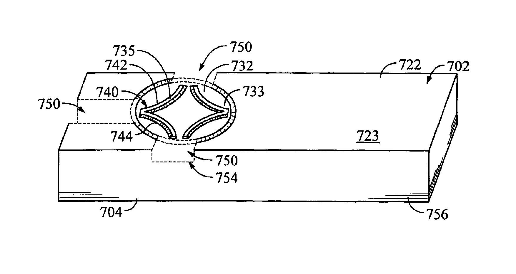
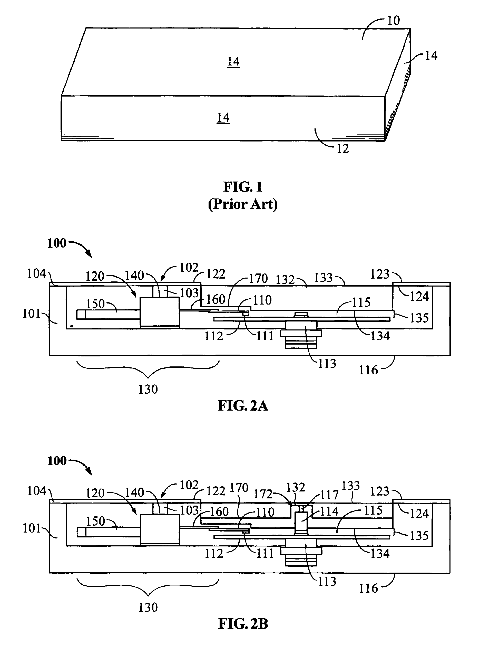
With reference now to FIG. 2A, FIG. 2A is a side-sectional view of a hard disk drive (HDD) 100, which includes a disk drive cover 102 that provides for disk shrouding, and in some embodiments heat dissipation, according to embodiments of the present invention. The disk drive 100 includes a head disk assembly (HDA) 101 and a printed circuit board assembly (PCBA) (not shown). As is known, the PCBA includes circuitry for processing signals and controlling the operations of the disk drive. The HDA 101 includes a base 116 and a disk drive cover 102 that may be attached to the base 116 to collectively house either a single disk 112 or a disk stack including multiple disks, a spindle motor 113 attached to the base 116 for rotating the disk 112 (or disk stack), a h...


PUM


Abstract

Disclosed is a disk drive cover that provides improved disk shrouding and heat dissipation. Part of the cover is recessed relative to the rest and may be substantially circular. The recessed portion may be located approximately adjacent to at least one disk and may be substantially coextensive with at least one disk. Further, the internal side of the recessed portion may be at a vertical depth sufficient enough to shroud at least one disk. Additionally, the recessed portion may further include at least a member that projects from the external side of the recessed portion, such as approximately arcuate-shaped members or approximately rectangular-shaped members, to aid in heat dissipation.

Description

BACKGROUND OF THE INVENTION1. Field of the InventionThe present invention relates to a disk drive cover for use with a disk drive. More particularly, the present invention relates to a disk drive cover for use with a disk drive that provides for disk shrouding and heat dissipation.2. Description of the Prior Art and Related InformationA huge market exists for hard disk drives for mass-market host computer systems such as servers, desktop computers, and laptop computers. To be competitive in this market, a hard disk drive should be relatively inexpensive, and should accordingly embody a design that is adapted for low-cost mass production. Further, there exists substantial competitive pressure to continually develop hard disk drives that have increasingly higher storage capacity, that provide for faster access to data, and at the same time conform to decreasingly smaller exterior sizes and shapes often referred to as “form factors.” Specific methods that are presently being employed t...

Claims


Application Information

Patent Timeline
IPC IPC(8): G11B33/02G11B33/14
CPCG11B33/022G11B33/148G11B33/142
Inventor CODILIAN, RAFFISINGH, DALWINDER
Owner WESTERN DIGITAL TECH INC
Why Eureka
Try Eureka