System and method for controlling data flow direction in a memory system

a memory system and data flow technology, applied in the field of memory systems, can solve the problems of limiting the interchangeability of various existing memory components and enormous development costs

Inactive Publication Date: 2005-03-01
INTEL CORP
View PDF12 Cites 86 Cited by
  • Summary
  • Abstract
  • Description
  • Claims
  • Application Information

AI Technical Summary

Problems solved by technology

The cost requiring specifically designed memory devices 80-95 to match the memory controller 50, and vice versa, cre

Method used


Image

  • System and method for controlling data flow direction in a memory system
  • System and method for controlling data flow direction in a memory system
  • System and method for controlling data flow direction in a memory system

Examples


Embodiment Construction

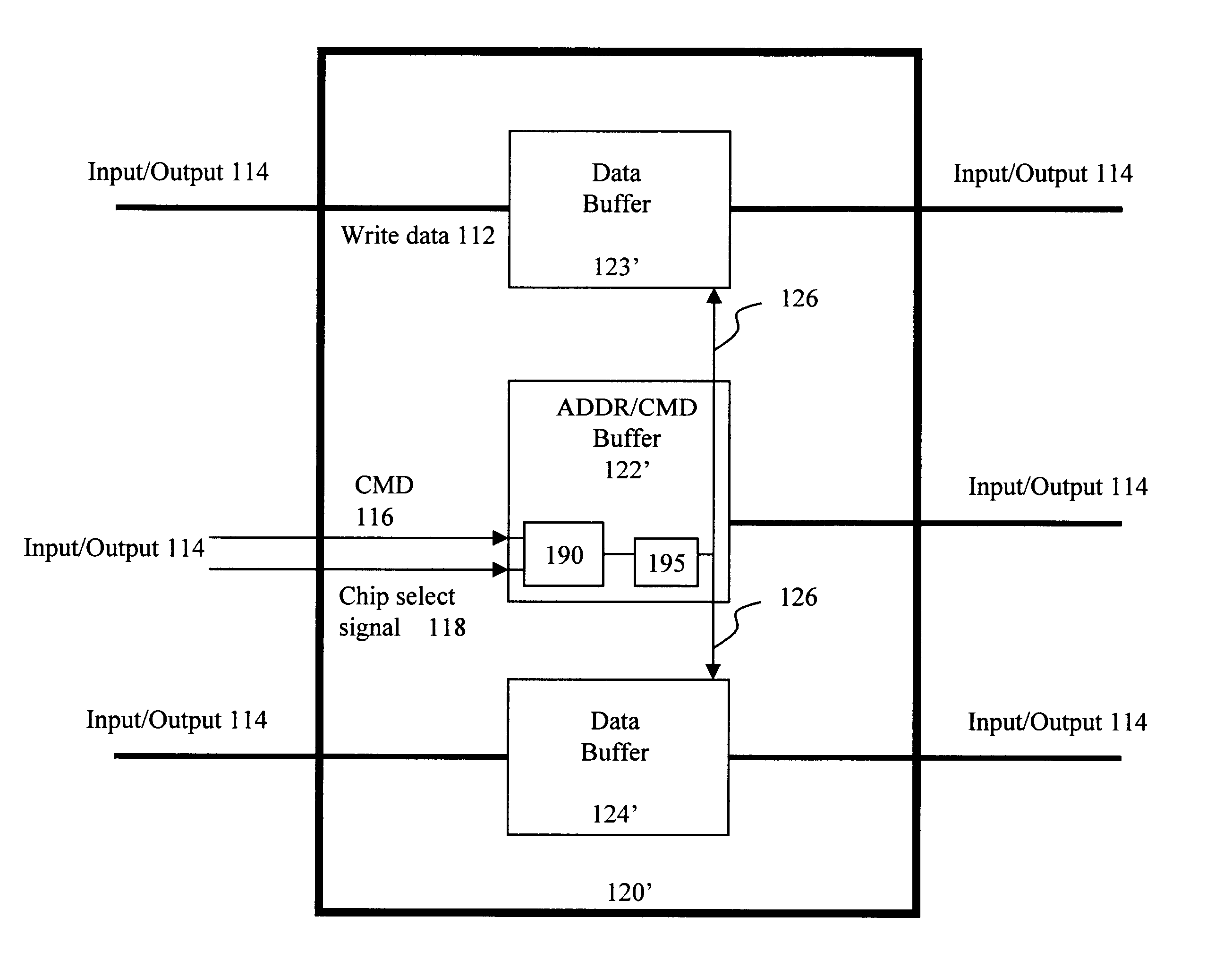
FIG. 3 illustrates a diagram of a memory system according to an embodiment of the present invention and in which embodiments of the present invention may function. The memory system 100 comprises a memory controller 110, a buffer 120, and memory devices 130-145. The buffer 120 is an external buffer(s) or register(s) that has the functionality of reducing the impedance seen by the memory controller 110. The memory controller 110 is coupled to the buffer 120, which is being further coupled to the memory devices 130-145, such as DRAM devices. Although the Input / Output connection lines 114 are represented as single lines to the buffer 120, and to the memory devices 130-145, each represented line 114 may in fact be a plurality of lines. The memory controller 110 may, for example, be a chipset central processing unit, and it is adapted to transmit different information—e.g., data, address information, command information—to the memory devices 130-145 via the buffer 120. The memory control...


PUM


Abstract

A system and method for controlling the direction of data flow in a memory system is provided. The system comprising memory devices, a memory controller, a buffering structure, and a data flow director. The memory controller sends data, such as read-data, write-data, address information and command information, to the memory devices and receives data from the memory devices. The buffering structure interconnects the memory device and the memory controller. The buffering structure is adapted to operate in a bi-directional manner for the direction of data flow therethrough. The data flow director, which may reside in the buffering structure, the memory controller, the memory devices, or an external device, controls the direction of data flow through the buffering structure based on the data transmitted from the memory controller or the memory device.

Description

BACKGROUND OF THE INVENTION1. Field of the InventionThe present invention generally relates to a memory system, and in particular, to a system and method for controlling the direction of data flow in a memory system having a buffering structure interconnecting a memory controller and memory devices. The memory devices may, for example, be dynamic random access memory (DRAM) devices.2. Related ArtA typical memory system includes a memory controller and memory devices, such as DRAMs, coupled thereto. In some systems, a processor performs memory controller functions. As used herein, the term memory controller includes such a processor. FIG. 1 illustrates a prior art memory system having memory devices 80-95 residing on memory modules. The memory modules are connected to a memory controller 50 via connectors 60, 70. In such a system, it is required that each component operates with the same interface voltage and frequency. Therefore, the memory controller 50 is manufactured to operate w...

Claims


Application Information

Patent Timeline
IPC IPC(8): G06F12/00G06F13/16
CPCG06F13/1673
Inventor DODD, JAMES M.WILLIAMS, MICHAEL W.
Owner INTEL CORP
Why Eureka
Try Eureka