Ratchet wrench

Inactive Publication Date: 2005-03-08
CHEN SHWU RUU
View PDF2 Cites 20 Cited by
  • Summary
  • Abstract
  • Description
  • Claims
  • Application Information

AI Technical Summary

Benefits of technology

The present invention is to mitigate and/or obviate

Problems solved by technology

However, the conventional ratchet wrench can withstand a smaller torque, so that it is easily broken due to an excessive torque.
In addition, the rotation angle of the r

Method used


Image

  • Ratchet wrench
  • Ratchet wrench
  • Ratchet wrench

Examples


Embodiment Construction

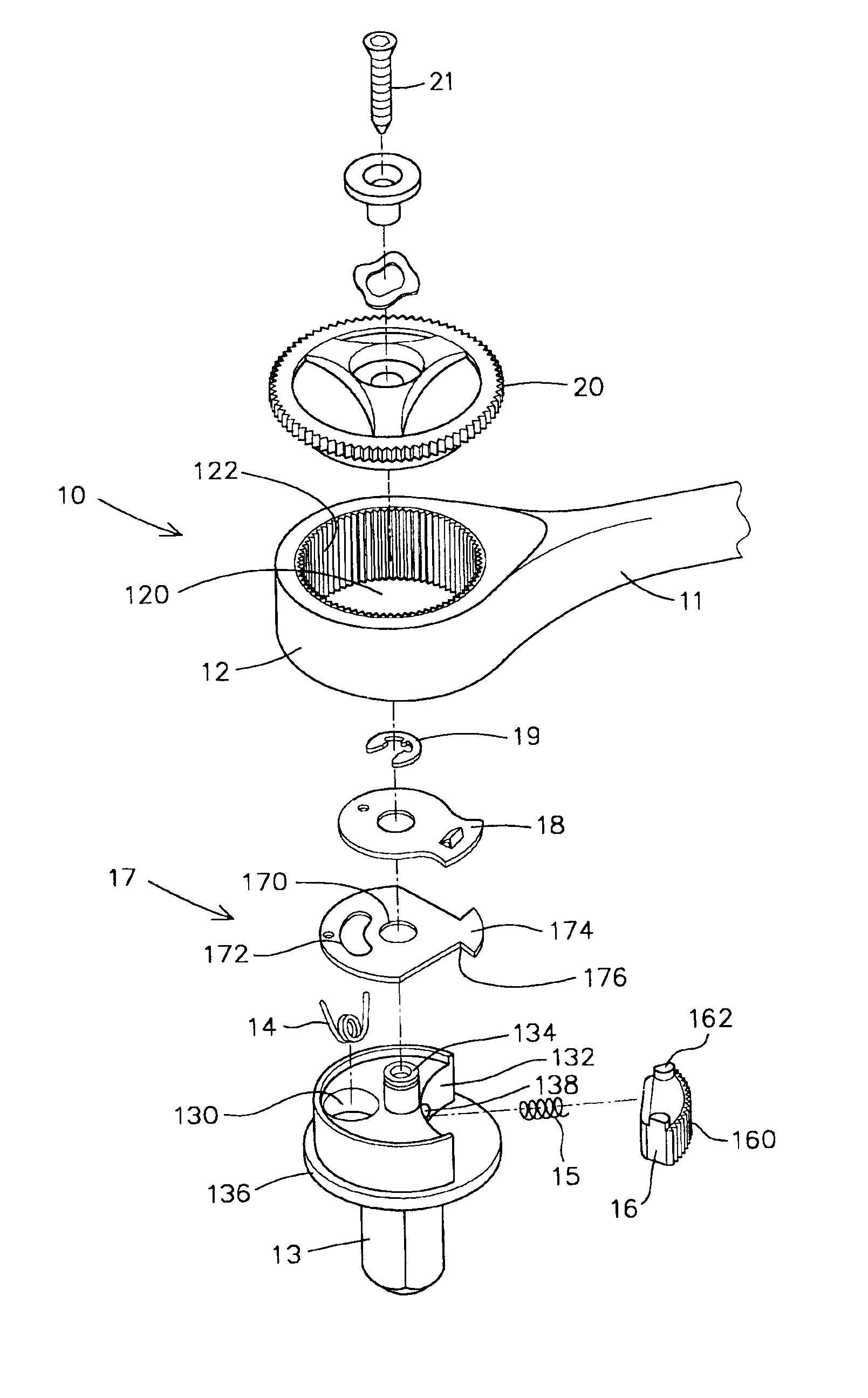
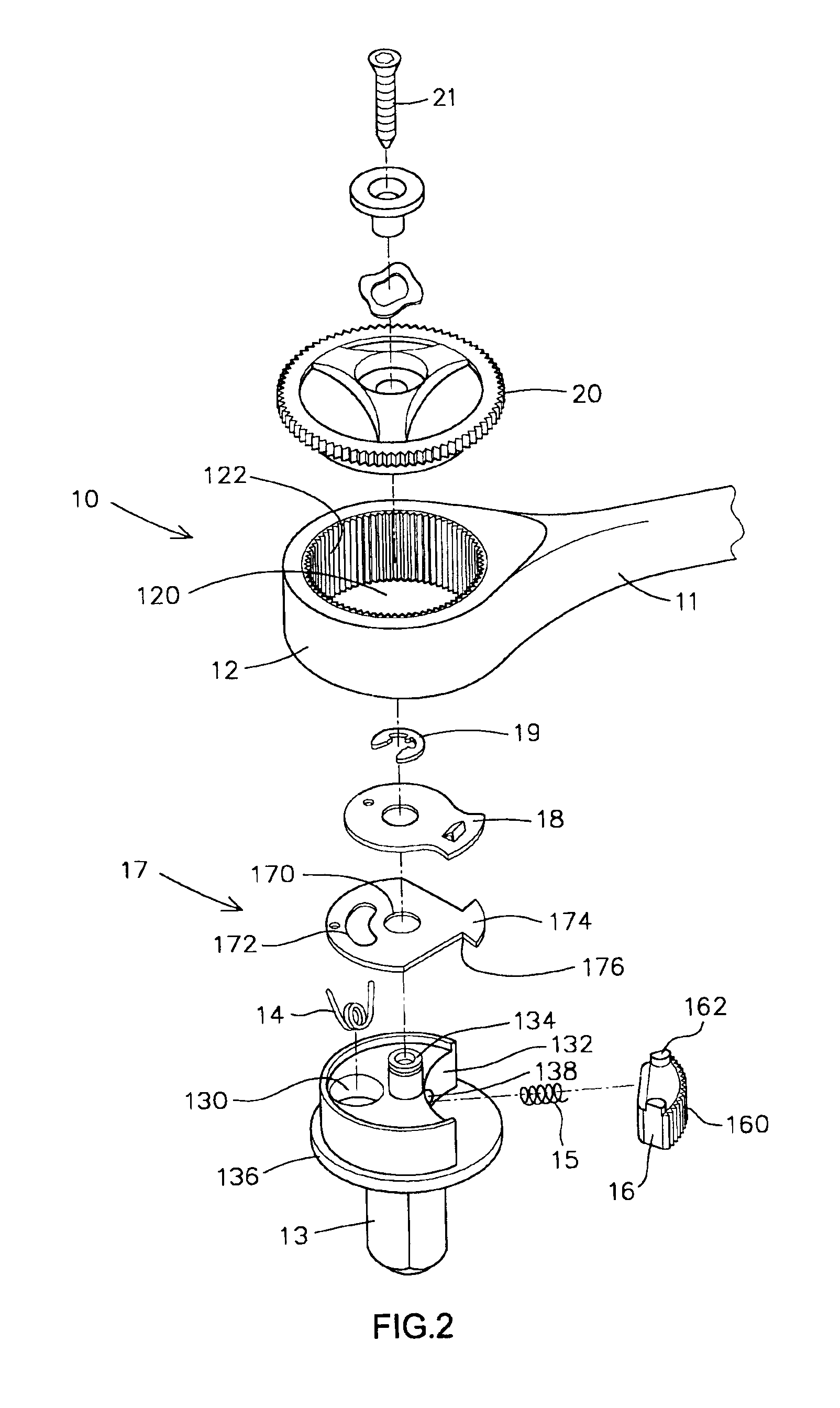
Referring to the drawings and initially to FIGS. 2-5, a ratchet wrench in accordance with the preferred embodiment of the present invention comprises a wrench body 10, an operation body 13, a limit plate 17, a pawl member 16, a cover plate 18, a snap ring 19, and a rotation member 20.

The wrench body 10 includes a handle 11 having an end formed with a drive head 12 having an inner wall formed with a receiving chamber 120 having a periphery formed with a plurality of ratchet teeth 122.

The operation body 13 is rotatably mounted in the receiving chamber 120 of the drive head 12 and has a first side formed with an arc-shaped opening 132 and a second side formed with a receiving recess 130 for receiving a torsion spring 14. The opening 132 of the operation body 13 has a wall formed with a receiving hole 138. The operation body 13 has a top formed with a protruding threaded support rod 134 and a bottom formed with an urging disk 136 rested on a bottom of the drive head 12 of the wrench bod...


PUM


Abstract

A ratchet wrench includes a wrench body, an operation body, a limit plate, a pawl member, a cover plate, a snap ring, and a rotation member. The pawl member is rotated by the limit plate, so that the engaging teeth of the pawl member mesh with the ratchet teeth of the drive head, and the operation body is operated in one direction only by rotation of the drive head. Thus, the ratchet wrench that can be operated easily and conveniently, thereby facilitating the user operating the ratchet wrench.

Description

BACKGROUND OF THE INVENTION1. Field of the InventionThe present invention relates to a ratchet wrench, and more particularly to a ratchet wrench that can be operated easily and conveniently.2. Description of the Related ArtA conventional ratchet wrench in accordance with the prior art shown in FIG. 1 comprises a wrench body 30 including a handle 31 having an end formed with a drive head 32 having an inner wall formed with a receiving chamber 320 having a periphery formed with a plurality of ratchet teeth 322, an operation body 33 rotatably mounted in the receiving chamber 320 of the drive head 32 and having a top formed with a screw bore 330, a pawl member 38 mounted on the operation body 33 and having a side formed with a plurality of engaging teeth 380 meshing with the ratchet teeth 322 of the drive head 32, a rotation member 34 rotatably mounted on a top of the drive head 32 of the wrench body 30, a screw 36 extended through the rotation member 34 and screwed into the screw bore ...

Claims


Application Information

Patent Timeline
IPC IPC(8): B25B13/00B25B13/46
CPCB25B13/465
Inventor CHEN, SHWU RUU
Owner CHEN SHWU RUU
Why Eureka
Try Eureka