
Drive mechanism for agricultural planters

a technology for agricultural planters and drive mechanisms, which is applied in the direction of analogue processes, instruments, and plants, can solve the problems of reducing the yield of seeds, so as to achieve the effect of reducing the loss of seeds and fertilizers, reducing the cost of production, and ensuring the quality of production

Inactive Publication Date: 2005-03-08
BLUE LEAF I P +1
View PDF5 Cites 39 Cited by
  • Summary
  • Abstract
  • Description
  • Claims
  • Application Information

AI Technical Summary

Benefits of technology

It is another object of this invention to provide a planter drive mechanism that both coordinates the delivery of both seed and fertilizer materials to the operating speed of the planter and provides a convenient manner in which to change the rate of application of either the seed or fertilizer materials.
It is a further object of this invention to provide a disc mower conditioner incorporating a modular disc cutterbar which is durable in construction, inexpensive of manufacture, carefree of maintenance, facile in assemblage, and simple and effective in use.

Problems solved by technology

This type of apparatus does not provide an adequate control of the dispensing of the seeds and fertilizer as a change in speed of operation of the tractor, thus affecting the forward speed of operation of the planter, the drive for the seeds and fertilizer does not change, resulting in a greater or lesser than desired seed spacing or spaces with no seeds planted at all.
When the tractor comes to a stop, the inertia of the mechanism keeps the delivery system working for a period of time, thus producing a substantial loss of both seeds and fertilizer.
The loss of seeds and fertilizer increases the cost of production and decreases productivity with respect to the different agricultural crops to be planted with the planter.

Method used


Image

  • Drive mechanism for agricultural planters
  • Drive mechanism for agricultural planters
  • Drive mechanism for agricultural planters

Examples


Embodiment Construction

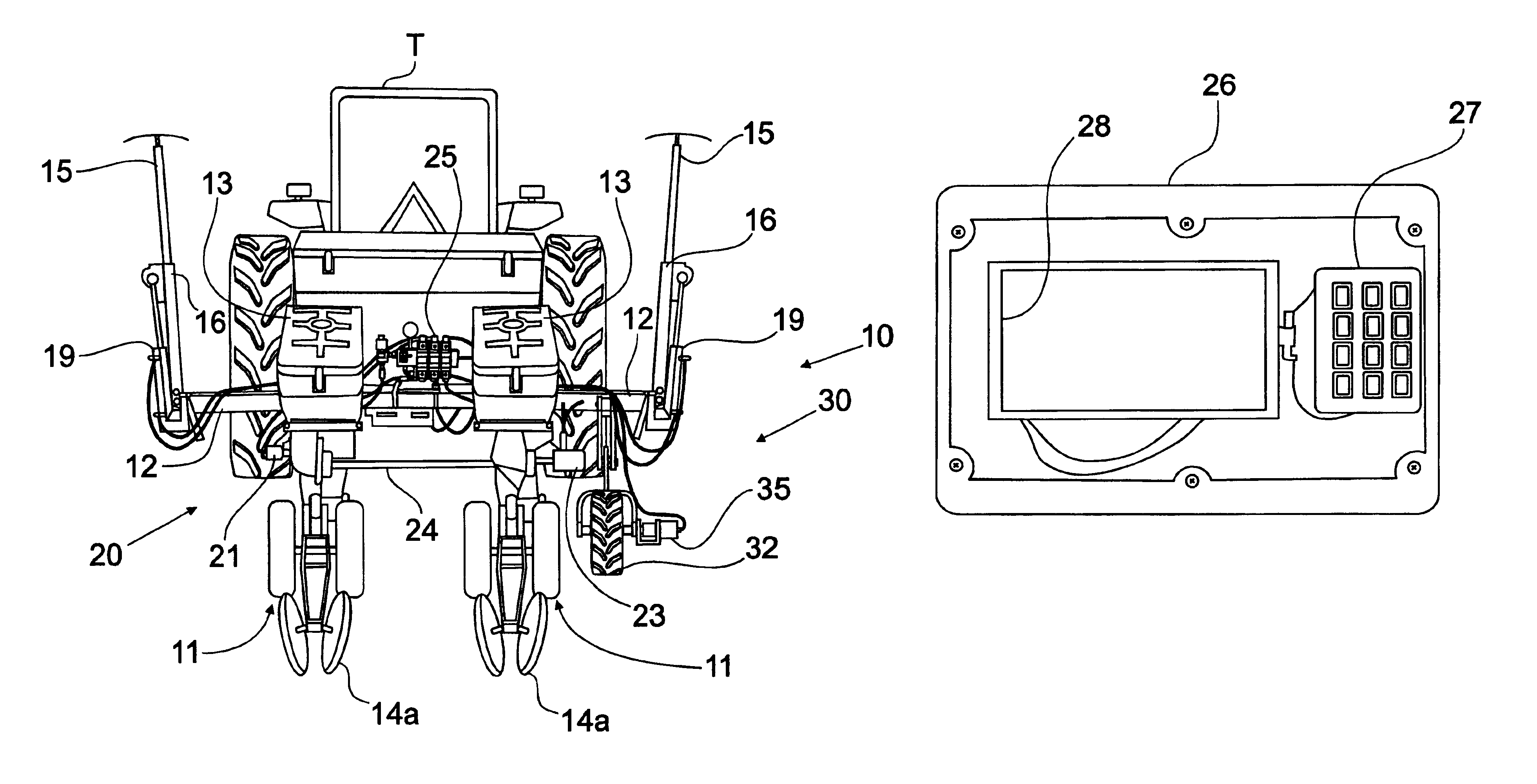
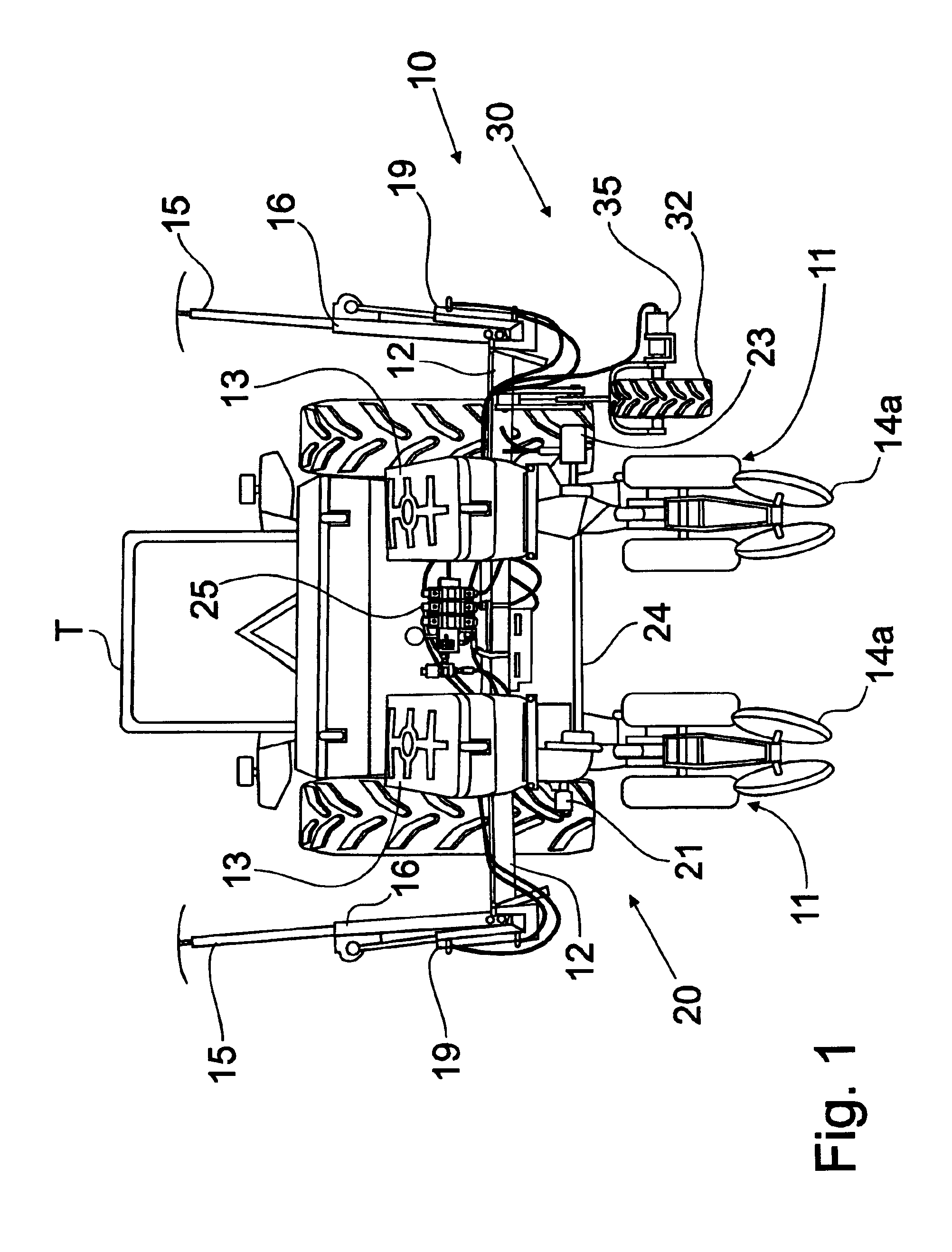
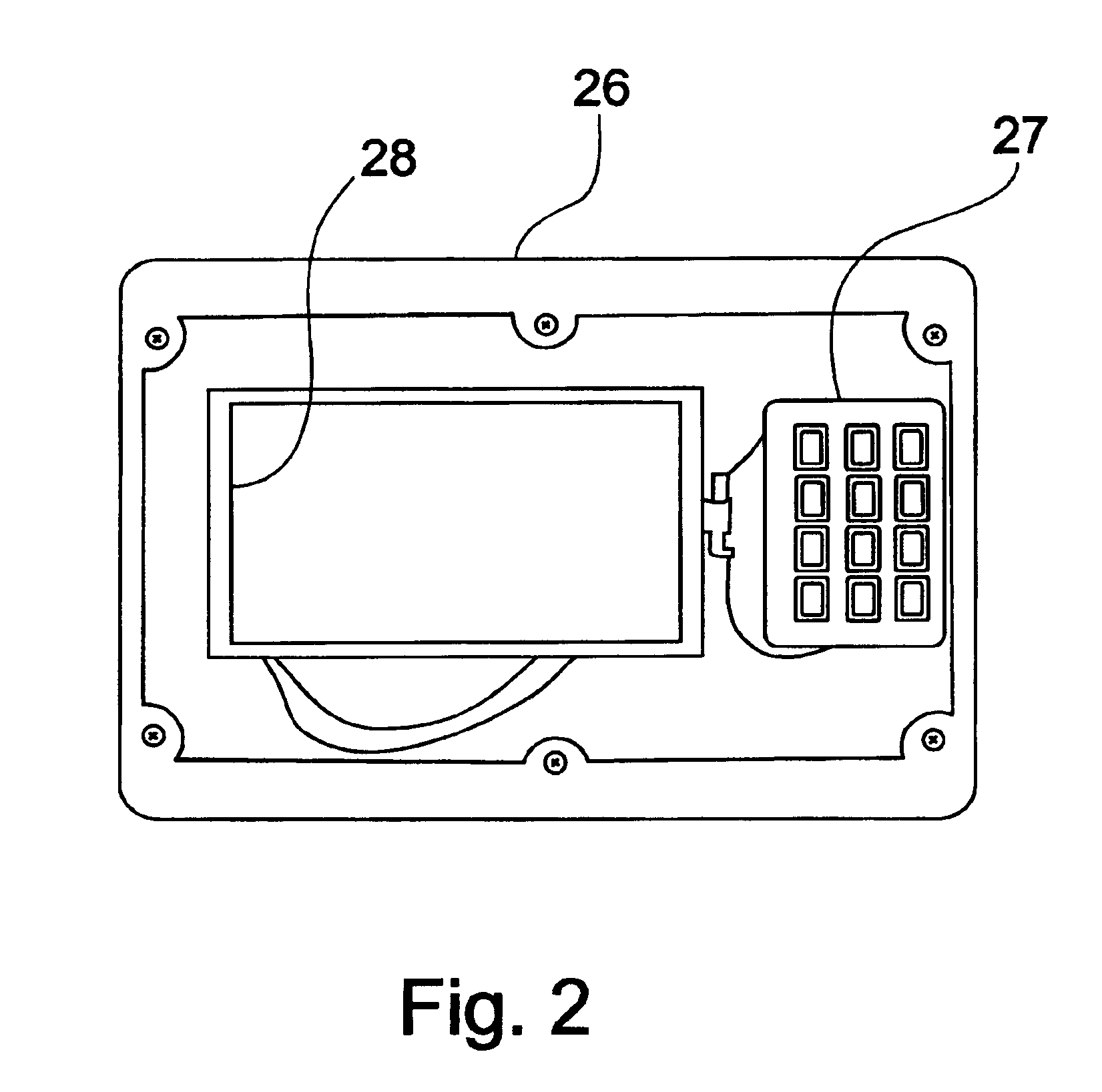
Referring first to FIG. 1, an overall view of the agricultural planter incorporating the principles of the instant invention can best be seen. Any left and right references are used as a matter of convenience and are determined by standing at the rear of the planter 10 facing the forward direction of travel which is the direction in which FIG. 1 is oriented. The planter 10 is mounted to the rear of a tractor T that provides motive and operational power for the planter 10. One skilled in the art will recognize that the planter 10 shown in FIG. 1 is a two row planter, but that the principles of the instant invention are applicable to much larger planters 10, including those planters operable to plant 20 or more rows. The planter 10 is provided with a pair of opposing field markers 15 pivotally mounted on the transverse frame 12 of the planter 10. The field markers 15 are generally conventional in construction and are formed of an arm 16 that is movable between a raised transport or no...


PUM


Abstract

A drive mechanism for an agricultural planter includes a first electronic controller, a second electronic controller, a hydraulic valve manifold, hydraulic drives for the seed and fertilizer hoppers, and a feedback sensor from the hydraulic drives to the second electronic controller. The first electronic controller is located in the cab of the tractor connected to the planter, while the second electronic controller is mounted on the planter to control the operation of the hydraulic drives. The feedback sensors provide data as to the operation of the hydraulic drives. Another sensor associated with the forward speed of the planter also provides input to the second electronic controller so that the second controller can coordinate the operational speed of the hydraulic drives to provide the rate of application of the seed and fertilizer products desired by the operator. Changes in the rate of application of either the seed or fertilizer materials can be accomplished through input to the first electronic controller.

Description

BACKGROUND OF THE INVENTIONThis invention relates generally to improved apparatus for the delivery of particulate material, including seed and fertilizer, to the ground, and, more particularly, to the use of an automated delivery apparatus that delivers precise quantities of particulate material as a function of the speed at which the planter is operated and the parameters established for such delivery.In conventional agricultural planters, seed and fertilizer products are distributed from separate hoppers through a metering device for delivery through a tube to fall by gravity to the ground and into a furrow formed therein for receipt of the seed and fertilizer. Seed particles are engaged by a singulator that operates to singulate the seeds so that the seeds can be dropped at a prescribed or desired rate through the delivery tube to the furrow. The quantities of the particulate fertilizer and seed material are to be monitored and delivered to the ground in a prescribed manner, incl...

Claims


Application Information

Patent Timeline
IPC IPC(8): A01C19/04A01C19/00
CPCA01C19/04Y10S111/90Y10S111/921Y10S111/922Y10S111/903
Inventor SANDOVAL, JAIME ARANACERVANTES, FRANCISCO PEREZMENDOZA, IVAN GABRIEL SALCEDO
Owner BLUE LEAF I P
Learn More