Device for applying a spot embossing pattern to a web of multi-ply tissue paper

a tissue paper and pattern technology, applied in the direction of lamination, mechanical working/deformation, lamination apparatus, etc., can solve the problem of long changeover time, and achieve the effect of high flexibility of the device, low cost and high cos

Inactive Publication Date: 2005-03-08
SCA HYGIENE PROD AB
View PDF10 Cites 27 Cited by
  • Summary
  • Abstract
  • Description
  • Claims
  • Application Information

AI Technical Summary

Benefits of technology

The invention resides in that the device for applying a spot embossing pattern to a web of multi-ply tissue paper comprises a marrying roll and a spot embossing unit directly cooperating with the marrying roll and being positioned against it. The spot embossing unit comprises a spot embossing roll with a raised embossing pattern on its circumferential surface. In other words, the spot embossing unit is incorporated in the ply bonding section of the paper converting machine but still provided as a separate unit so that it is easily accessible and easy to change. This provides a high flexibility to satisfy different customers who wish to be provided with different spot designs. Moreover, the rollers are relatively cheap and can be exchanged between different paper converting machines. Since the marrying roll acts as an anvil roll for the spot embossing roll of the spot embossing unit, it serves a double function. This reduces the number of components in the paper converting machine.
According to a preferred embodiment of the invention, the spot embossing unit is rotating freely and driven by the rotation of the marrying roll. This measure further simplifies the device because it is not necessary to provide a driving unit and a control for the driving unit of the spot embossing device.
According to a preferred embodiment of the invention, the spot embossing unit comprises one shaft which extends over the full width of the tissue web and carries a single spot embossing roll. In other words, one rotating shaft extending over the full width of the tissue web and having the same length as e.g. the marrying roll, carries an annular spot embossing roll in contact with the marrying roll. The advantage of this embodiment lies in the short changeover time for changing the spot embossing roll. In comparison to the alternative embodiments described below, the provision of one single embossing roll incurs higher costs.
According to an alternative embodiment of the invention, the spot embossing unit comprises a rotating shaft which extends over the full width of the tissue web and carries a plurality of spot embossing rolls. There is one single shaft onto which a plurality of individual spot embossing rolls are arranged. The individual spot embossing rolls can have the shape of short annular rings which are arranged in a longitudinal direction over the single rotating shaft and can be regrouped to realize a plurality of different spot embossing patterns on the tissue web. This embodiment of the spot embossing unit contributes to the high flexibility of the device which requires only short changeover times and, by use of low cost spot embossing rolls, can be specifically adapted to the customers' needs. Moreover, the provision of single spot embossing rolls enables a flexible adaption to desired production quantities. If a certain number of product webs are cut from the tissue web, two or more different design patterns can be produced at the same time. The inventive spot embossing unit enables a quick adjustment of the production output by changing the number of individual ring-like spot embossing roll which are used on one single rotating shaft.
Alternatively, the spot embossing unit comprises a plurality of individual spot embossing rolls each of which are carried by individual shafts. This alternative system even increases the flexibility of the spot embossing unit. If it is desired to change the distribution of design bands on the tissue paper web, it is no longer necessary to remove the individual spot embossing rolls from the full-length rotating shaft and to bead the desired spot embossing rolls again onto the shaft. A single spot embossing roll can easily be exchanged simply by removing and exchanging it.
According to a preferred embodiment of the invention, the spot embossing unit is removably mounted to a machine frame of a paper converting machine. This further increases the flexibility of the spot embossing unit, because it can be easily shifted from one paper converting machine to another one.

Problems solved by technology

However, if it is desired to change the spot embossing pattern, the whole embossing roll has to be exchanged resulting in rather long changeover times to exchange the rolls having a weight up to several tons.

Method used


Image

  • Device for applying a spot embossing pattern to a web of multi-ply tissue paper
  • Device for applying a spot embossing pattern to a web of multi-ply tissue paper
  • Device for applying a spot embossing pattern to a web of multi-ply tissue paper

Examples


Embodiment Construction

In the following description, identical or similar elements will be designated throughout the Figs. with the same reference numerals.

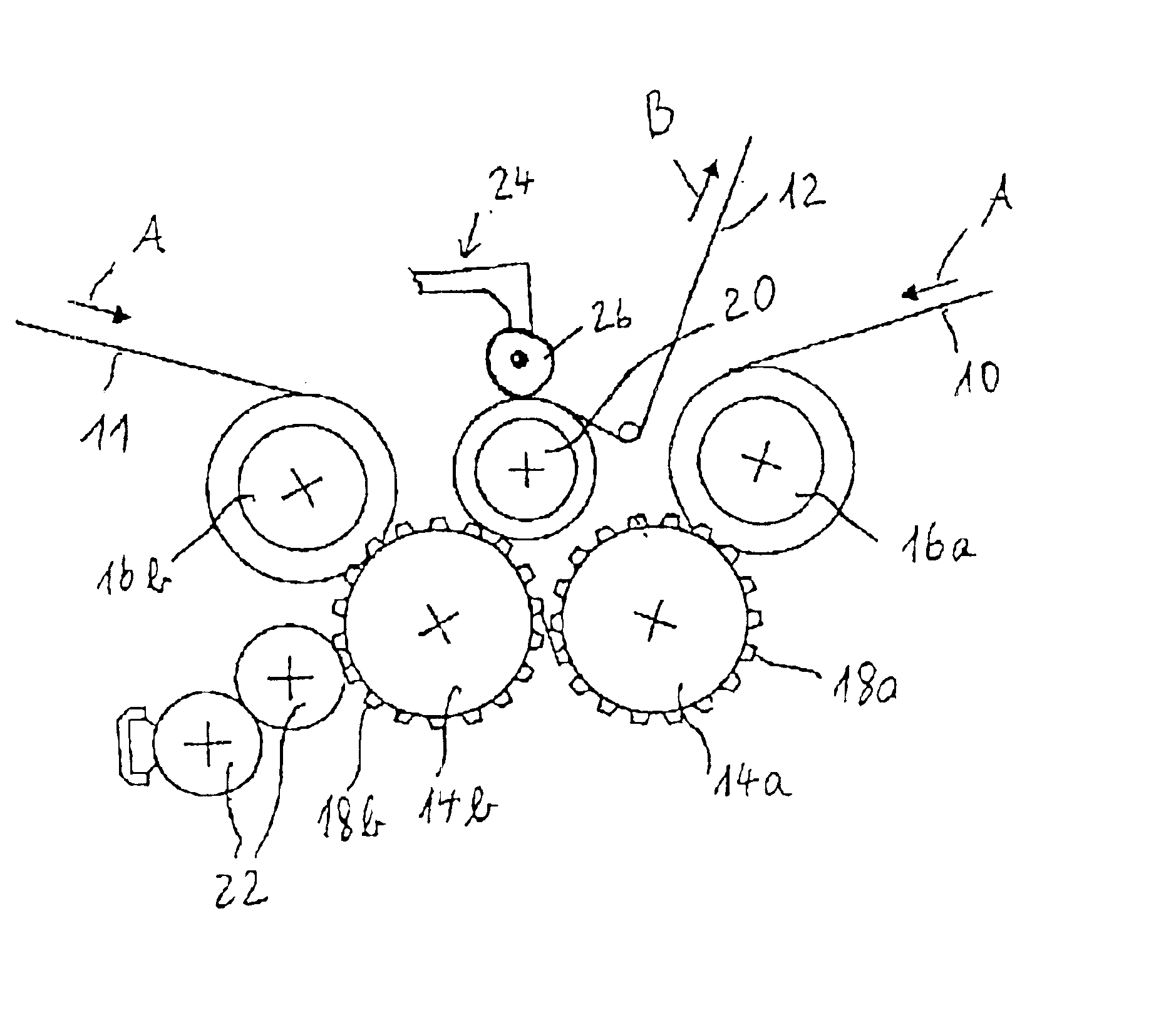
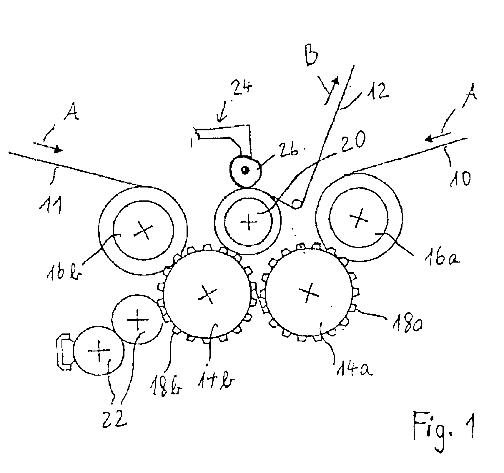
FIG. 1 schematically shows the position of a spot embossing unit within a paper converting machine. Although there are two plies of tissue paper in the example shown, it should be apparent to those skilled in the art that the multi-ply tissue paper to be processed in the inventive device might consist of more than two plies of tissue paper.

The two plies 10, 11 of tissue paper are fed in the direction of arrow A and pass through the nip between rubber rolls 16a, 16b and corresponding steel embossing rolls 14a, 14b. The steel embossing rolls 14a, 14b are driven and in registration with each other such that the microembossing protrusions 18a, 18b on their peripheral surface apply a microembossing pattern of small protuberances to the tissue webs 10, 11 such that these two plies can be brought together in a nested configuration. The rubber rollers 16a, 16b...


PUM

PropertyMeasurementUnit
widthaaaaaaaaaa
mechanicalaaaaaaaaaa
regular structureaaaaaaaaaa

Abstract

A device for applying a spot embossing pattern to a web of multi-ply tissue paper being processed in a paper converting machine comprises a marrying roll and a spot embossing unit cooperating and being positioned against the marrying roll. The spot embossing unit comprises a spot embossing roll with a raised embossing pattern on its circumferential surface. The at least two plies of tissue web are combined with a marrying roll and pass between the marrying roll and the spot embossing unit.

Description

FIELD OF THE INVENTIONThe invention relates to a device and a method for applying a spot embossing pattern to a web of multi-ply tissue paper being processed in a paper converting machine.TECHNICAL BACKGROUNDThere are different possible methods for applying an embossing pattern to tissue paper. The most common are point to point, nested, structural embossing or double embossing random laminate. In each of these cases, the embossing pattern is applied by use of one or more steel rolls in combination with rubber rolls. The rubber rolls have a yielding surface. A raised embossing pattern on the steel roll elastically presses into the rubber roll so that the tissue paper fed between the rubber roll and the steel roll is imparted an embossing pattern. All plies of a multi-ply tissue paper are thus embossed and are normally glued together. Alternatively, it is possible to provide a mechanical ply-bonding by edge-embossing both plies of tissue paper together.In order to meet customer prefe...

Claims


Application Information

Patent Timeline
Patent Type & Authority Patents(United States)
IPC IPC(8): B31F1/00B31F1/07
CPCB31F1/07B31F2201/0723B31F2201/0753Y10T156/1741B31F2201/0776B31F2201/0787Y10T156/1023B31F2201/0774
Inventor HEIN, FERDINANDHARLACHER, HARALDLEONHARDT, JOACHIM
Owner SCA HYGIENE PROD AB
Why Eureka
Try Eureka