Capillary evaporator

Inactive Publication Date: 2005-03-08
MIKROS MFG
View PDF16 Cites 88 Cited by
  • Summary
  • Abstract
  • Description
  • Claims
  • Application Information

AI Technical Summary

Benefits of technology

In another aspect, the present invention is directed to a capillary evaporator comprising a capillary wick having a first face and a second face spaced from the first face. A first bridge confronts the first face of the capillary wick and has a plurality of first internal passageways each having a first cross-sectional area. The plurality of first internal passageways become less numerous in a direction away from the capillary wick and the first cross-sectional areas of the plurality of first

Problems solved by technology

This creates a large pressure drop for the liquid that effectively limits the maximum liquid flow rate, thereby limiting the heat transport capacity of the heat pipe.
Increasing the thickness of the wick translates into a higher thermal resistance at the evaporator and, perhaps more limiting, an increase in the liquid superheat at the interface between the inner surface of the tube and the wick.
Eventually, the superheat at the base of the wick becomes too large and boiling takes place in the wick, leading to a drying out of the wick.
When the wick dries out, the performance of the wick

Method used


Image

  • Capillary evaporator
  • Capillary evaporator
  • Capillary evaporator

Examples


Example

DETAILED DESCRIPTION OF THE DRAWINGS

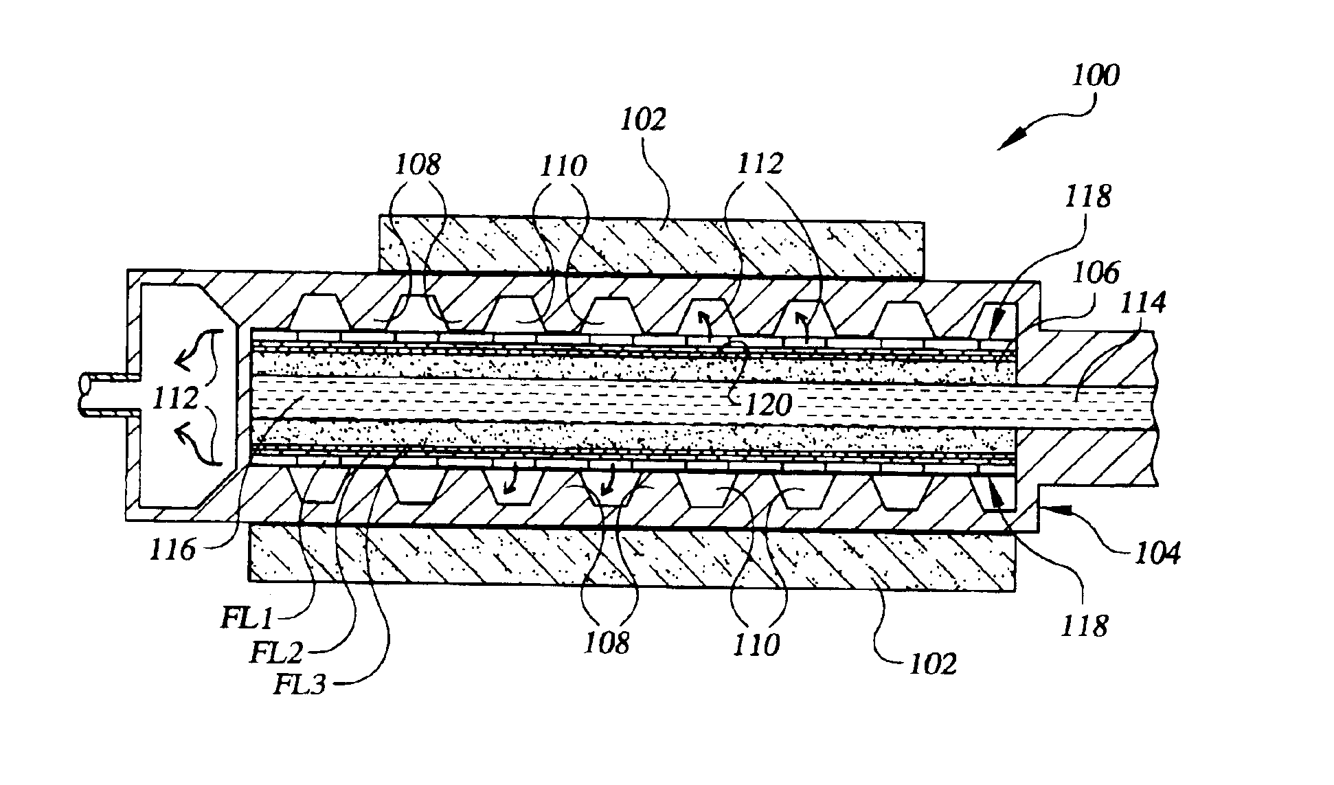
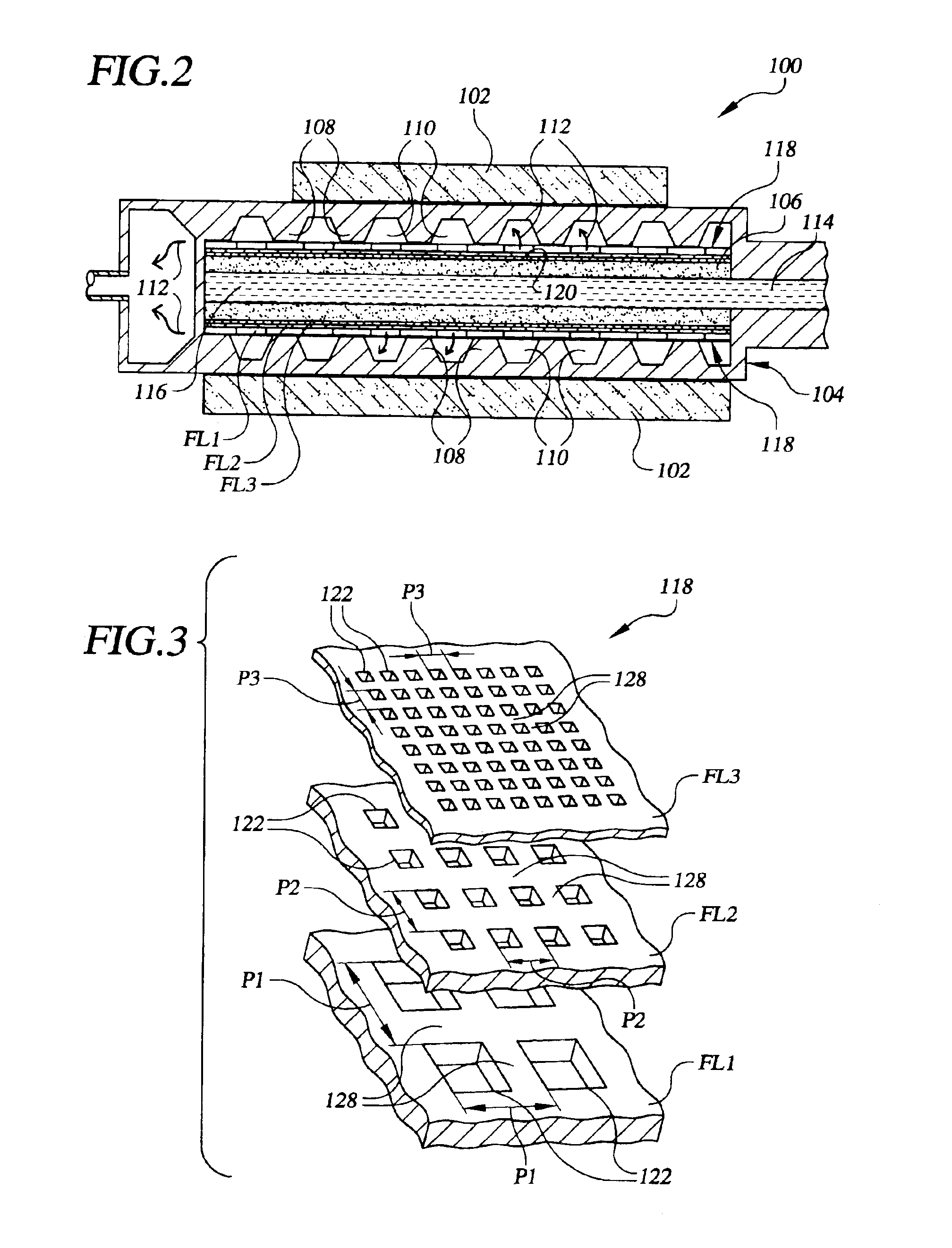
Referring now to the drawings, FIG. 2 shows, in accordance with the present invention, a capillary evaporator, which is identified generally by the numeral 100. Like evaporator 20 discussed in the background section, above, capillary evaporator 100 may be incorporated into a two-phase heat-transfer system, such as the loop heat pipe (LHP) and capillary pumped loop (CPL) systems mentioned above, among others. Capillary evaporator 100 may be any size and / or shape suitable for interfacing with any of a variety of heat sources, such as heat source 102, that is desired to be cooled. Those skilled in the art will appreciate the variety of shapes and / or sizes of capillary evaporator 100 that may be made in accordance with the present invention and that the various capillary evaporators shown and described in the present application are generally provided only to illustrate the various aspects of the present invention and not to limit the scope of the inv...


PUM

PropertyMeasurementUnit
Timeaaaaaaaaaa
Thicknessaaaaaaaaaa
Thicknessaaaaaaaaaa

Abstract

A capillary evaporator (100) for removing heat from a heat source (102), particularly under high heat-flux conditions. The capillary evaporator includes a housing (104) having a plurality of ribs (108) in thermal communication with the heat source when the heat source is present. The ribs define a plurality of vapor channels (110) for receiving vapor (112) caused by the vaporization of working fluid (114) within the evaporator. A capillary wick (106) is located within the housing in spaced relation to the ribs. A bridge (118) interposed between the capillary wick and ribs thermally communicates heat from the ribs to the wick and fluidly communicates the vapor from the wick to the vapor channels. The bridge includes a plurality of fractal layers (FL) each having openings (122) and webs (128) that are scaled in size and number with respect to the immediately adjacent fractal layer and are arranged so that the openings in adjacent layers overlap one another.

Description

FIELD OF THE INVENTIONThe present invention relates generally to the field of thermal management systems. More particularly, the present invention is directed to a capillary evaporator.BACKGROUND OF THE INVENTIONCapillary evaporators are used in a variety of two-phase thermal management systems. The primary difference between capillary evaporators and flow-through and kettle boilers is that nucleate boiling does not occur in evaporators, whereas it does in boilers. Instead, evaporation takes place in a capillary evaporator at a liquid-vapor interface held stable by a capillary wick structure. The liquid supplied to an evaporator is at a pressure lower than the vapor pressure, and the liquid is drawn into the evaporator by the capillary suction of the wick.A common capillary evaporator configuration is the configuration used in heat pipes. A conventional heat pipe typically consists of a tube containing a porous capillary wick layer in contact with the inner surface of the tube. One ...

Claims


Application Information

Patent Timeline
IPC IPC(8): F28D15/02
CPCF28D15/0233Y10T29/49353F28D15/00B23P6/00F28D15/02
Inventor VALENZUELA, JAVIER A.
Owner MIKROS MFG
Why Eureka
Try Eureka