
Automotive vehicle occupant protection system

Inactive Publication Date: 2005-03-08
HONDA MOTOR CO LTD
View PDF148 Cites 29 Cited by
  • Summary
  • Abstract
  • Description
  • Claims
  • Application Information

AI Technical Summary

Benefits of technology

In view of such problems of the prior art, a primary object of the present invention is to provide a vehicle occupant protection system which can improve the protection of the vehicle occupant at the time of a vehicle crash for a given dynamic stroke or a deformation stroke of a front part of the vehicle body.
Preferably, the mass member comprises a flywheel which provides a large amount of inertia without taking up any significant amount of space. The actuator may comprise wire including a first end connected to a working end of the main actuator unit, an intermediate part wound around a rotary shaft having the flywheel integrally or otherwise functionally connected thereto, and a second end attached to the moveable end of the seat belt. In particular, by choosing the rotary shaft to have an appropriate diameter, it is possible to magnify the inertia effect of the flywheel at will. The inertia effect gets greater as the diameter of the rotary shaft is reduced.

Problems solved by technology

As it is not possible to eliminate a certain amount of resiliency and slack in the seat belt, the deceleration of the vehicle occupant reaches a peak level only when the vehicle occupant has moved forward a certain distance under the inertia force and the elongation of the seat belt has reached its maximum extent.
According to a normal vehicle body structure, owing to the presence of a crushable zone in a front part of the vehicle and a slack and elongation of the restraint system such as a seat belt, it takes a certain amount of time for the impact of a crash to reach the vehicle occupant.
As a result, the waveform of the crash reaction or the vehicle body deceleration is small in an early phase, and then gets greater in a later phase so that the vehicle occupant deceleration cannot be adequately reduced.
However, such previous proposals can only maintain the vehicle body deceleration at an approximately constant level at most, and are unable to provide a more effective deceleration waveform.
In such a case, because the shoulder anchor and buckle anchor experience different decelerations, the springs cannot be simply combined or the decelerations acting on the shoulder anchor and buckle anchor cannot be simply equated to the vehicle body deceleration.
However, it was found due to the nature of its structure which relies on the generation of high pressure gas that such an actuator alone may not be able to produce a desired time history of the deceleration of the vehicle occupant.

Method used


Image

  • Automotive vehicle occupant protection system
  • Automotive vehicle occupant protection system
  • Automotive vehicle occupant protection system

Examples


Embodiment Construction

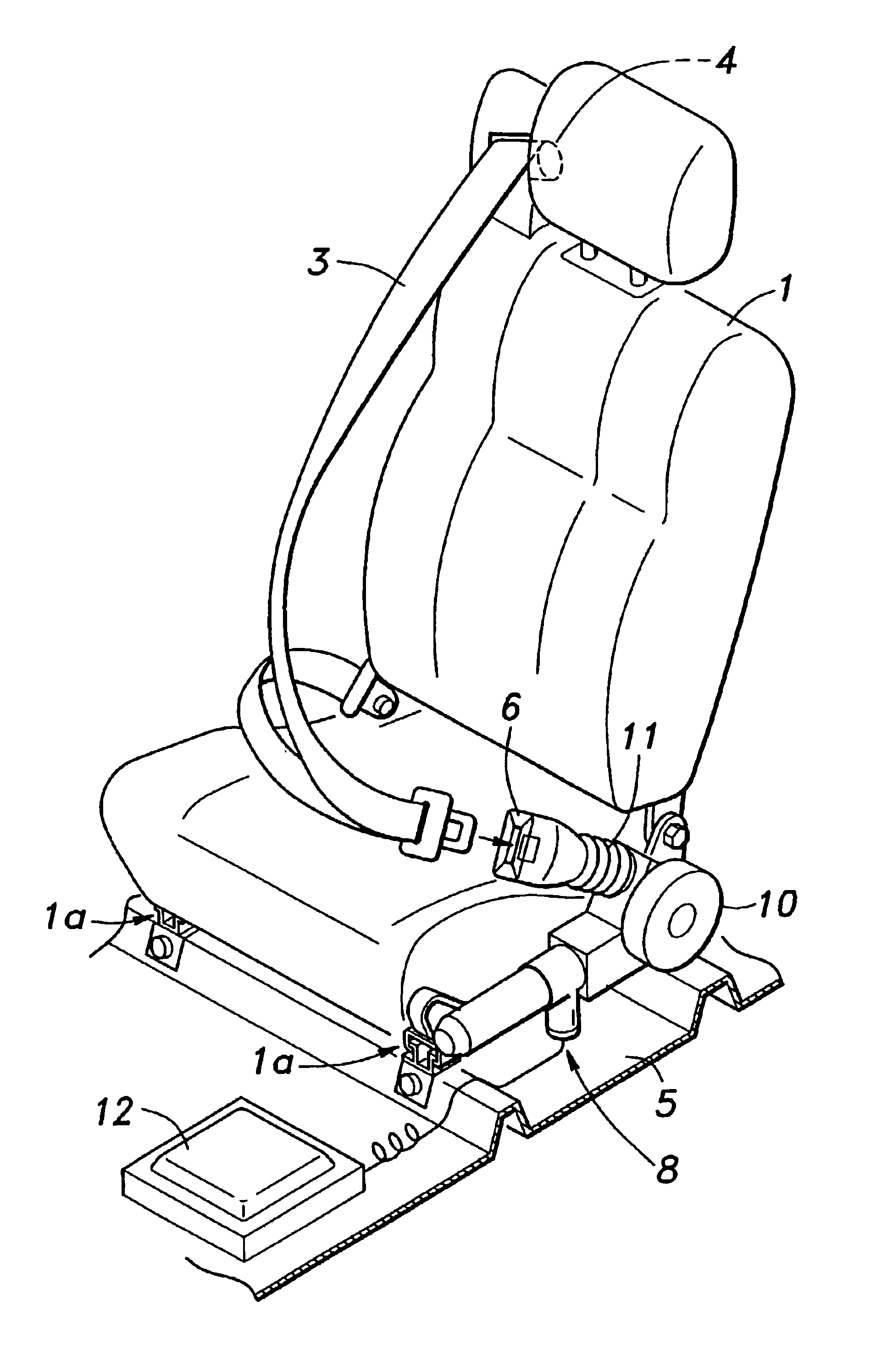
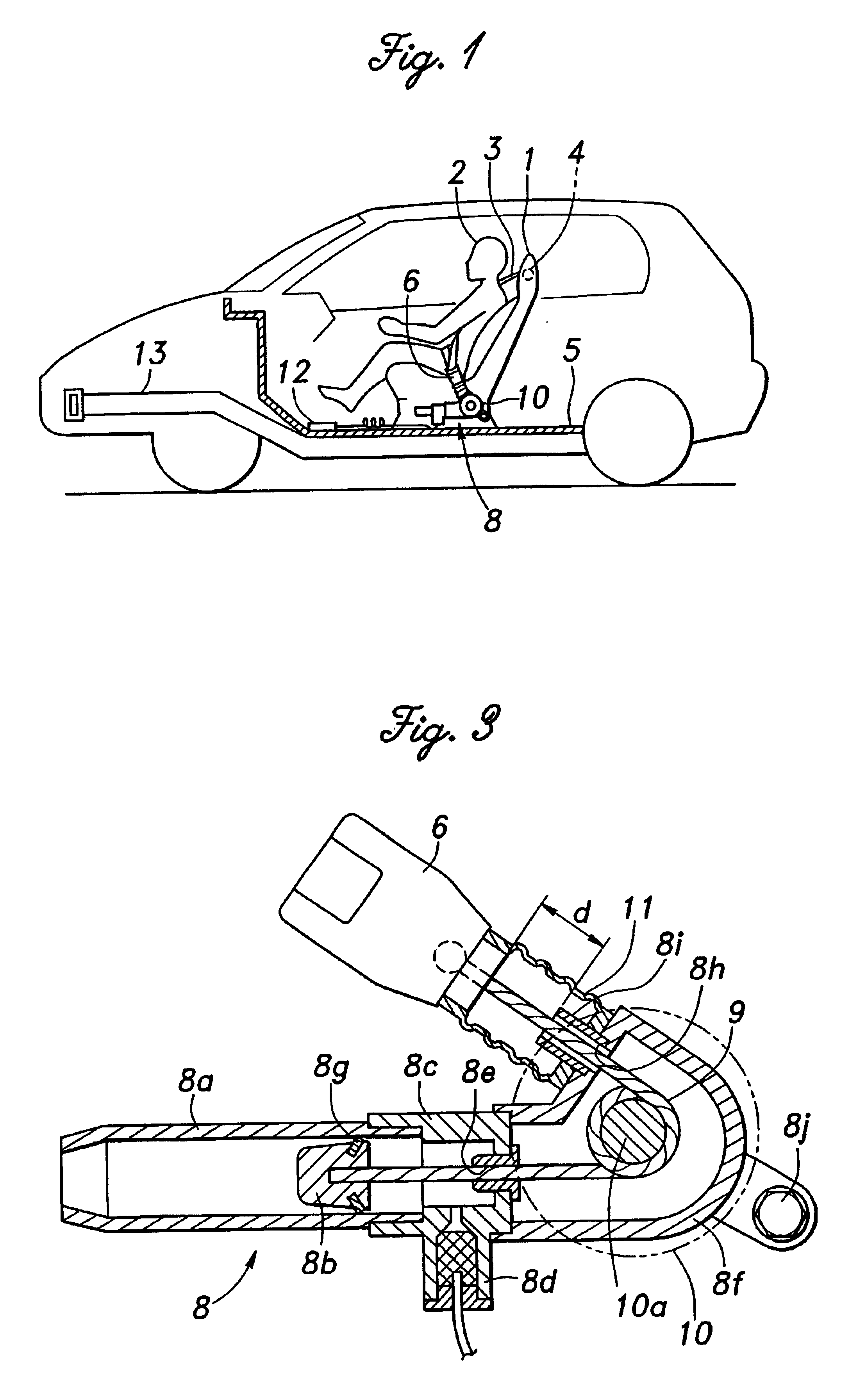
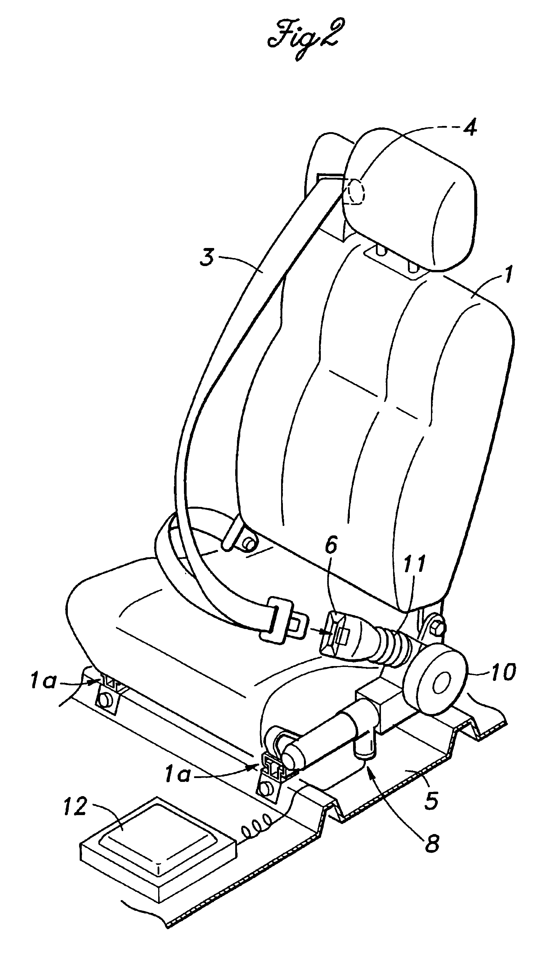
FIG. 1 schematically illustrates the overall structure of a vehicle incorporated with a vehicle occupant protection system embodying the present invention. The vehicle occupant protection system includes a seat belt 3 for restraining the vehicle occupant 2 to the seat 1. As shown in FIG. 2 also, the seat belt 3 has three anchor points, and an end of the seat belt is connected to a retractor 4 integrally provided in a shoulder part of the seat 1, another end fixedly attached to a side of the seat bottom on the same side as the shoulder anchor, and an intermediate part having a tongue plate that is latched to a buckle 6 attached to the side of the seat bottom on the other side of the shoulder anchor. Therefore, the vehicle occupant 2 who is seated in the seat 1 is integrally restrained to the seat 1 by the seat belt 3. The seat 1 is attached to a floor 5 via seat rails 1a so as to be adjustable in the fore-and-aft direction.

An actuator 8 is integrally attached to a side of the seat bo...


PUM


Abstract

An end of a seat belt is connected to an actuator that can selectively remove a slack from the seat belt. The actuator includes a main actuator unit, a flywheel which provides a maximum inertia effect for a given space, and a cushioning member for decelerating a movement of the moveable end of the seat belt following a certain initial travel of the moveable end. The main actuator unit produces an early rise in the vehicle occupant deceleration, and the cushioning member smoothly connects the time history of the vehicle occupant deceleration to a ride-down condition whereby the deceleration acting on the vehicle occupant is favorably spread over time, and the maximum level of the deceleration can be minimized. The flywheel contributes to a favorable shaping of the time history of the vehicle occupant deceleration.

Description

TECHNICAL FIELDThe present invention relates to a vehicle occupant protection system for improving the crash safety of the vehicle.BACKGROUND OF THE INVENTIONIn recent years, motor vehicles have been often fitted with a pretensioner device which positively increases the tension of the seat belt for restraining the vehicle occupant at the time of a crash and improves the protection of the vehicle occupant. The deceleration acting on the vehicle occupant who is restrained to the seat by a restraint device such as a seat belt starts rising only when the forward inertia force acting on the vehicle occupant at the time of the crash has started to be supported by the seat belt. As it is not possible to eliminate a certain amount of resiliency and slack in the seat belt, the deceleration of the vehicle occupant reaches a peak level only when the vehicle occupant has moved forward a certain distance under the inertia force and the elongation of the seat belt has reached its maximum extent. ...

Claims


Application Information

Patent Timeline
IPC IPC(8): B60R22/195B60R22/18B60R22/26B60R22/28B60R22/22B60R22/46
CPCB60R22/1952B60R22/26B60R22/1955B60R22/1953
Inventor MOTOZAWA, YASUKI
Owner HONDA MOTOR CO LTD
Learn More