Supercharge Your Innovation With Domain-Expert AI Agents!

Door latch mechanism and associated components for a self-cleaning oven

a self-cleaning oven and latch mechanism technology, applied in the field of self-cleaning ovens, can solve the problems of current locking mechanism undesirably stalling, higher cost, and higher strength or force of locking mechanism, and achieve the effect of reducing the likelihood of stalling, reducing the speed of latching, and increasing the mechanical advantage at a clamping

Inactive Publication Date: 2005-03-08
EMERSON ELECTRIC CO
View PDF39 Cites 9 Cited by
  • Summary
  • Abstract
  • Description
  • Claims
  • Application Information

AI Technical Summary

Benefits of technology

In this manner, a class N (or other) motor may be used as a driver. Additionally, the latching linkage is configured to decrease latch speed at clamping or latching point. This increases the mechanical advantage at a clamping. As well, the likelihood of stalling is reduced. Further, the present latching linkage requires less torque to operate.

Problems solved by technology

Tolerance stack-up on doors, frames and hinges of the oven uses up the compressibility of the seal of the door and can cause current locking mechanisms to undesirably stall.
Higher strength or force for the locking mechanism translates into a higher cost.
However, even with the reduction of force requirements and such direct drive mechanisms, the problem of stalling of the latch is still present.
A problem with such radial cams is that the thickness (height) of the drum stack would become too large to package the many switches that are now part of the locking mechanism in a convenient ganged array if the drum stack is too large, the locking mechanism becomes too thick for useful or practical packaging for ovens.
This can present a problem of correctly connecting the various spade connectors.

Method used


Image

  • Door latch mechanism and associated components for a self-cleaning oven
  • Door latch mechanism and associated components for a self-cleaning oven
  • Door latch mechanism and associated components for a self-cleaning oven

Examples


Embodiment Construction

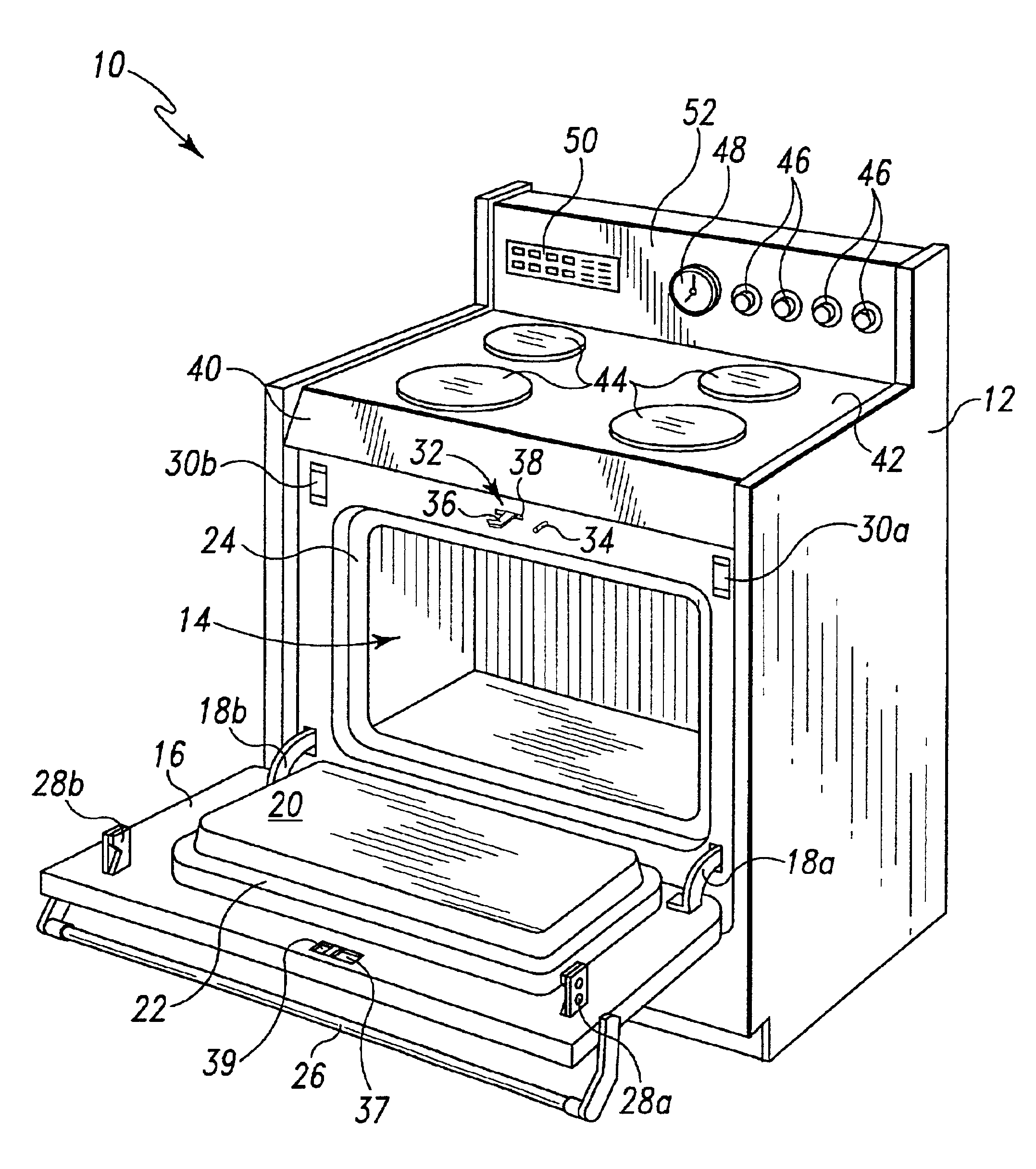
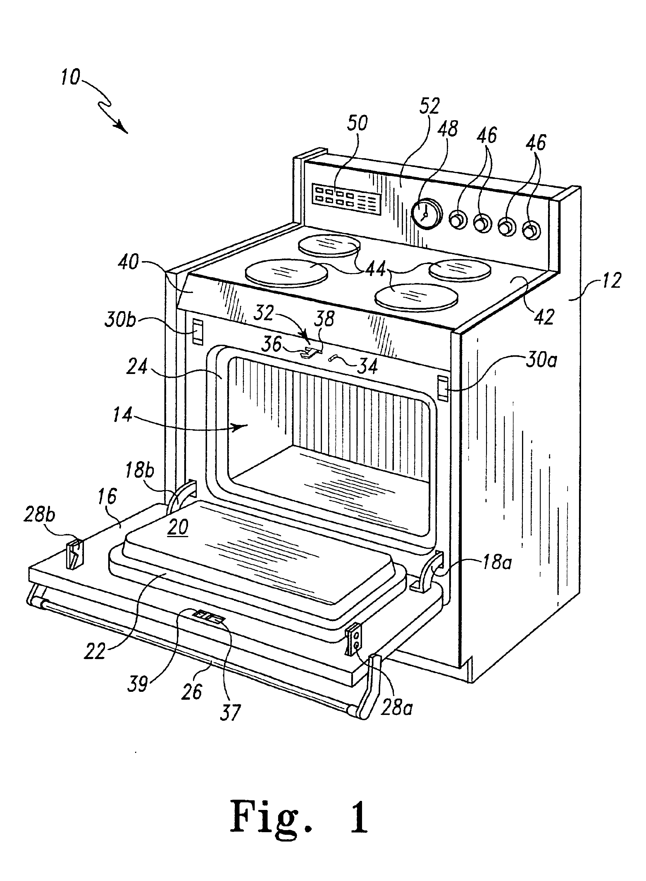
Referring to FIG. 1, there is depicted an oven, range, or stove (and as used hereinafter, collectively oven) generally designated 10, representing all forms of ovens, ranges, and stoves in which the subject inventions may be embodied. The oven 10 has a frame or body 12 that defines an oven portion or cooking chamber 14. The cooking chamber includes cooking elements (not shown) such as resistive heating elements, or the like such as is known. A door 16 is attached to the frame 12 by at least two hinges 18a and 18b that extend into the frame 12. The door 16 is adapted to open and close relative to the cooking chamber 14. Particularly, the door 16 is adapted to pivot into open and closed positions relative to the cooking chamber 14. The hinges 18a and 18b extend into the frame 12 and are configured to allow the door 16 to open and close. The hinges 18a and 18b also stop movement of the door 16 at the position shown in FIG. 1 (a fully open position). While not shown, the door 16 may inc...


PUM


Abstract

A door latching or locking mechanism or module for a self-cleaning oven includes latching linkage of the door latch module that enables use of lighter duty, less expensive motor. The mechanical advantage and vector optimization of the latching linkage avoids stalling especially from a locked position. The latching mechanism includes a plurality of switches having a corresponding plurality of terminals. The terminals are grouped or ganged to allow connection with a single connector interface. The switches are selectively actuable / de-actuable by a cam and cam plate that utilizes linear motion translated from rotational motion of a driven (motor) to selectively actuate and / or de-actuate the switches.

Description

FIELD OF THE INVENTIONThe present invention relates generally to self-cleaning ovens, and more particularly, to a door latch mechanism and associated aspects thereof for self-cleaning ovens.BACKGROUNDOvens that are self-cleaning are well known. Such self-cleaning ovens include a cleaning mode or cycle that is initiated by a user. The self-cleaning cycle generates intense heat inside the oven. The intense heat reduces food particles, grease, spills and splatter (collectively, build-up) inside the oven to ash. Once the cleaning cycle is complete, the resulting ash may then be easily wiped away.Because of the intense heat necessary to reduce such build-up to ash, self-cleaning ovens lock the oven door during the cleaning cycle to prevent access thereto. Self-cleaning ovens thus include a locking mechanism that keeps the oven door shut and locked during the cleaning cycle. While the locking mechanism may be manually actuated, most locking mechanisms in current self-cleaning ovens are au...

Claims


Application Information

Patent Timeline
IPC IPC(8): E05B17/22E05B17/00F24C15/02
CPCE05B17/0029F24C15/022E05B17/22Y10T292/0936Y10T292/1082Y10T292/0914Y10T292/0915Y10T292/1062
Inventor COLE, RONALD E.
Owner EMERSON ELECTRIC CO
Features
  • R&D
  • Intellectual Property
  • Life Sciences
  • Materials
  • Tech Scout
  • Unparalleled Data Quality
  • Higher Quality Content
  • 60% Fewer Hallucinations
Learn More