Safety candle and method of forming same

a safety candle and wick technology, applied in the field of candles, can solve the problems of difficult and expensive manufacturing, limited to container candles, and wicks and wick supports are commonly referred to as “flare-up” or “flash-over” and other problems, to achieve the effect of high melt temperatur

Inactive Publication Date: 2005-03-08
BYRD RALPH DWAYNE
View PDF29 Cites 61 Cited by
  • Summary
  • Abstract
  • Description
  • Claims
  • Application Information

AI Technical Summary

Benefits of technology

With the foregoing in mind, it is an object of the present invention to provide a candle having a wick support with flame snuffer capabilities and method of forming the same, which alleviates the disadvantages of the prior constructions as noted above. This object is accomplished by providing a plastic wick support, which in a first embodiment is directly molded around the lower end of the wick, and with the support being composed of a thermoplastic polymeric material having a high melt temperature. Also, the polymeric material preferably has incorporated therein a flame retardant that is released when the wick support is heated by the flame to a predetermined temperature below the melt temperature of the polymeric material.

Problems solved by technology

A distinct disadvantage of such wicks and wick supports is commonly referred to as “flare-up” or “flash-over”.
While such safety wax will generally prevent flare-up or flash-over, it is usable only in container-type candles and not self-supporting type candles and is difficult and expensive to manufacture.
While somewhat successful in preventing flash-over or flare-up, the attempts as described above are generally limited to container candles and rely solely upon fuel deprivation for extinguishing the flame.
Also, such attempts require special containers or additional elements which increase the cost of the candles.
While the candle as shown in FIGS. 5 and 6, and as described above, represents a significant improvement, it is not entirely satisfactory since the assembly of the button onto the wick is a time consuming operation which is usually conducted by hand, and the loose fitting of the button on the wick can result in mis-alignment of the button during the molding of the wax to embed the wick.

Method used


Image

  • Safety candle and method of forming same
  • Safety candle and method of forming same
  • Safety candle and method of forming same

Examples


second embodiment

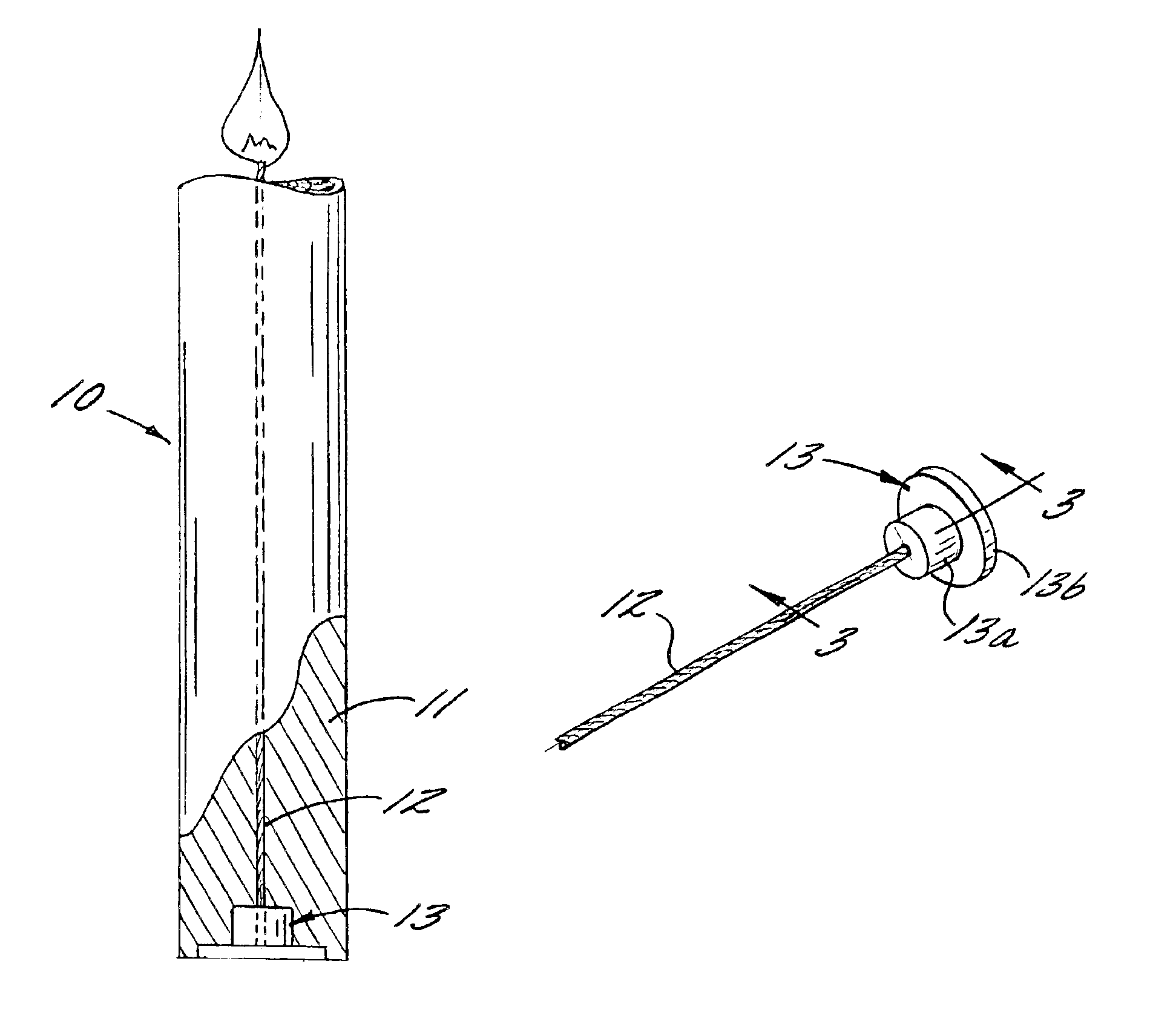
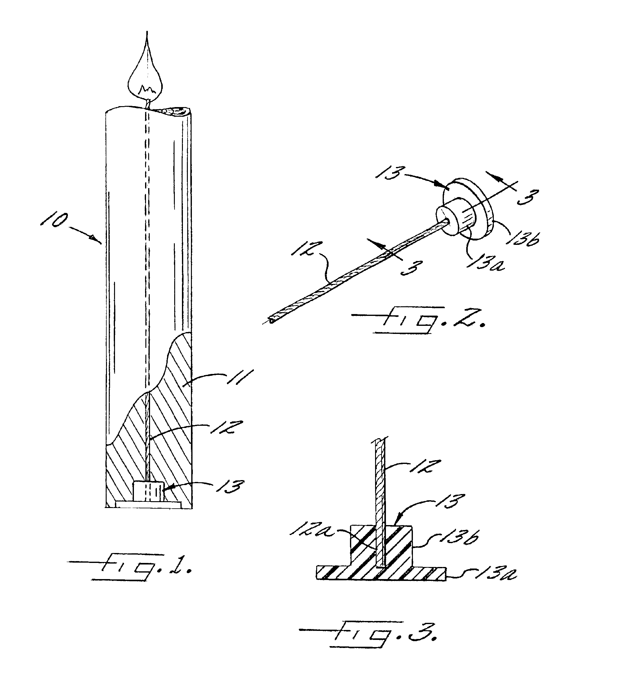
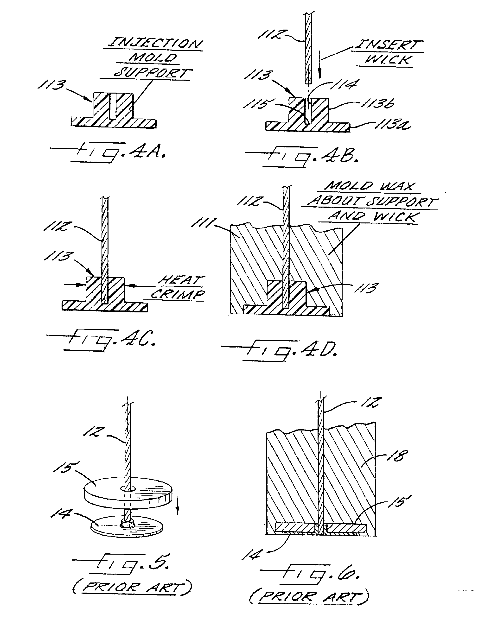
the prevent invention, and its method of manufacture are illustrated in FIGS. 4A-4D. In this embodiment, the wick support 113 is separately molded in a conventional injection molding machine, and the support includes a base or flange portion 113a and a cylindrical pedestal portion 113b of unitary one piece construction. Also, the support is molded so as to include a coaxial bore 114 which extends thereinto from the upper end. The bore 114 has a length which extends substantially the full length of the pedestal portion, and it includes a closed end 115. Alternatively, the bore could be formed by a drilling operation.

As illustrated in FIG. 4B, the lower end portion of a wick 112 is inserted coaxially into the bore of the support, with the end of the wick preferably abutting the closed end 115 of the bore 114.

Next, and as illustrated in FIG. 4C, the pedestal portion is crimped laterally so as to fixedly secure the wick 112 in the bore. Preferably, this crimping operation is accompanied...


PUM

PropertyMeasurementUnit
melting pointaaaaaaaaaa
melting temperatureaaaaaaaaaa
thicknessaaaaaaaaaa

Abstract

A safety candle and a method of forming the same which includes a coaxial wick having its lower end portion fixedly secured in an injection molded, thermoplastic wick support. The wick support may incorporate a flame retardant which can be mixed with the thermoplastic material of the support to aid in snuffing the flame. The wick support is preferably formed of a high melt polypropylene or a clear polycarbonate.

Description

FIELD OF THE INVENTIONThe present invention relates to candles and more particularly to safety candles and a method of forming same.BACKGROUND OF THE INVENTIONIt is conventional to form candles with a centrally positioned wick around which a fuel, such as wax, is poured and solidifies. The lower end portion of the wick is often attached to a wick support, base or sustainer. Typically, such a wick support is a metal disk with a central hole punched therein into which the lower end of the wick is inserted and the wick support is crimped around the wick. When the wax is poured around the wick, the wick support is embedded in the solidified wax.A distinct disadvantage of such wicks and wick supports is commonly referred to as “flare-up” or “flash-over”. This phenomenon occurs when the candle burns down to the wick support and molten wax is drawn upwardly through the central bore of the wick support and there is a flare-up or flash-over.Several attempts have been proposed to solve this p...

Claims


Application Information

Patent Timeline
Patent Type & Authority Patents(United States)
IPC IPC(8): C11C5/00
CPCC11C5/006
Inventor BYRD, RALPH DWAYNE
Owner BYRD RALPH DWAYNE
Why Eureka
Try Eureka