Method for producing a torsion spring

a torsion spring and spring technology, applied in the field of torsion spring production methods, can solve the problems of sensitivity to transverse stresses in two torsion spring cross sections

Inactive Publication Date: 2005-03-08
LITEF
View PDF3 Cites 27 Cited by
  • Summary
  • Abstract
  • Description
  • Claims
  • Application Information

AI Technical Summary

Problems solved by technology

The two torsion spring cross sections have the di

Method used


Image

  • Method for producing a torsion spring
  • Method for producing a torsion spring

Examples


Embodiment Construction

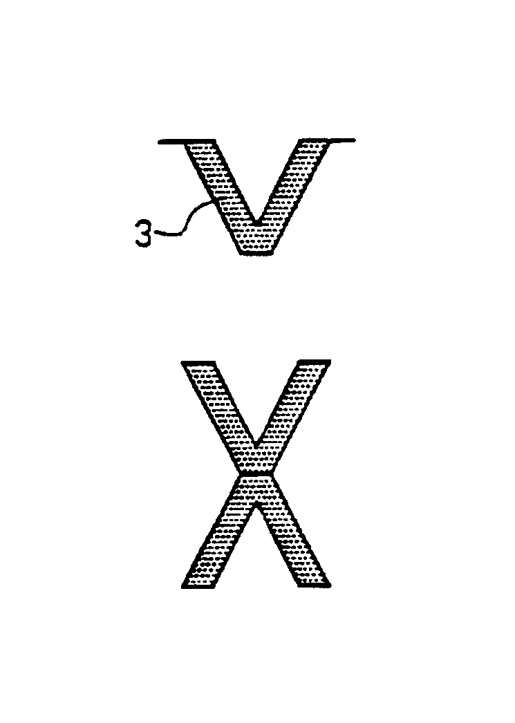
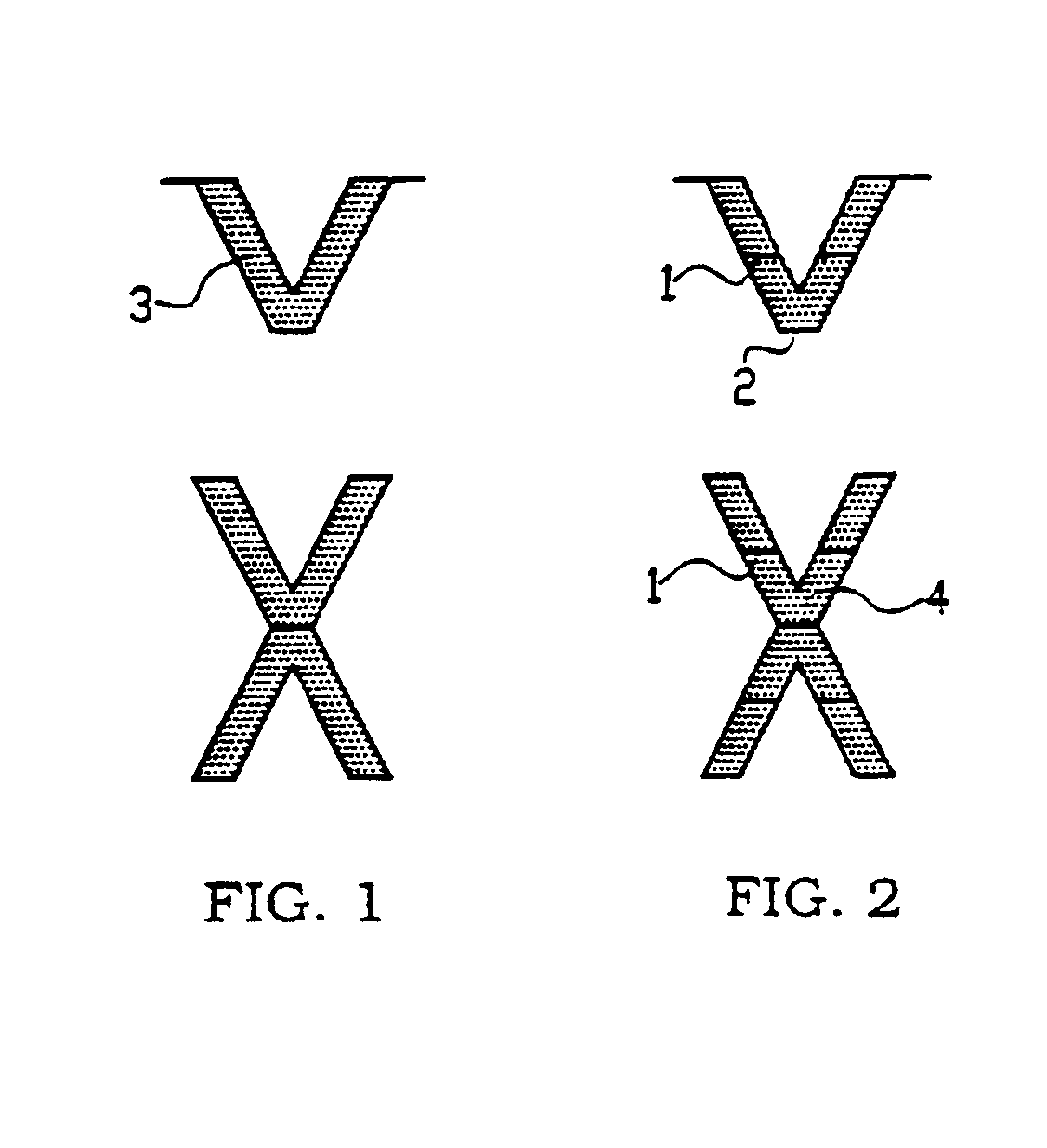
FIG. 1 illustrates a first method in accordance with the invention for producing a torsion spring with an X-shaped cross section from two wafers. In FIG. 1, the starting point for the method is two identical wafers, while in FIG. 2, which illustrates a second method in accordance with the invention, the starting point for the method is two wafer layer composites, separated or electrically insulated from one another along their common surface plane by an insulating layer 1. Strip-shaped etching masks 2 are applied in the lateral edge region of the wafers or the wafer composites. A spring 3 with a V-shaped cross section, which is laterally delimited by [111] planes, is then produced in the edge region of each wafer or wafer composite by anisotropic, wet-chemical etching. Two of the wafers or wafer composites which have been prepared with a V-shaped spring in this way are rotated through 180° with respect to one another and are then joined to one another oriented mirror image symmetric...


PUM

PropertyMeasurementUnit
Angleaaaaaaaaaa
Thicknessaaaaaaaaaa
Stiffnessaaaaaaaaaa

Abstract

A method for producing a silicon torsion spring capable, for example, of reading the rotation rate in a microstructured torsion spring/mass system. The system that is produced achieves a low torsional stiffness compared to a relatively high transverse stiffness in the lateral and vertical directions. The method proceeds from a wafer or wafer composite and, upon suitable mask coverage, a spring with a V-shaped cross section is formed by anisotropic wet-chemical etching which preferably extends over the entire wafer thickness and is laterally delimited only by [111] planes. Two of the wafers or wafer composites prepared in this way are rotated through 180° and joined to one another oriented mirrorsymmetrically with respect to one another, so that overall the desired X-shaped cross section is formed.

Description

BACKGROUND1. Field of the InventionThe present invention relates to methods for producing a torsion spring for a micromechanical torsion spring / mass system. More particularly, the invention pertains to the production of a torsion spring from two wafers or wafer composites that possesses low torsional relative to transverse stiffness in the lateral and vertical directions.2. Description of the Prior ArtSilicon torsion springs are known in various design variants in microstructuring. For example, C. Kaufman, J. Markert, T. Werner, T. Gessner and W. Dotzel in “Characterization of Material and Structure Defects on Micromechanical Scanners by Means of Frequency Analysis”Proceedings of Micro Materials (1995) p. 443, describe relatively long narrow strips, for example, for the articulated mounting of torsion mirrors. The spring cross section is of trapezoidal shape. Springs are formed on opposite wafer edges and produced by etching pits from the back surface during structuring of the sprin...

Claims


Application Information

Patent Timeline
IPC IPC(8): B81C1/00B81B3/00G01P15/08G01C19/56
CPCB81B3/0051G01P15/0888G01C19/56B81B2201/0242B81C2201/0133
Inventor WIEMER, MAIKHILLER, KARLABILLEP, DETLEFBRENG, UWERVRKO, BRUNOHANDRICH, EBERHARD
Owner LITEF
Why Eureka
Try Eureka