Vertical electrical downtilt antenna

a vertical electrical and antenna technology, applied in the direction of antennas, antenna details, substation equipment, etc., can solve the problems of relatively high cost of implementation, conventional sidelobe minimization, and relatively high cost of techniques

Inactive Publication Date: 2005-03-08
ARINC +1
View PDF16 Cites 121 Cited by
  • Summary
  • Abstract
  • Description
  • Claims
  • Application Information

AI Technical Summary

Benefits of technology

The present invention meets the needs described above in an antenna suitable for use as a wireless base station antenna that implements vertical electrical downtilt and sidelobe minimization. The antenna includes a multiple element array and a beam steering circuit including a variable power divider and a multi-beam beam forming network. The antenna also includes a power distribution network connecting the outputs of the beam steering circuit to the individual elements of the antenna array. The variable power divider may employ a single adjustable control element to divide an input voltage signal into a pair of complimentary amplitude voltage drive signals over a range of voltage amplitude division. In addition, the voltage drive signals may exhibit matched phase and constant phase delay through the variable power divider over the range of voltage amplitude division. This configuration produces voltage drive signals for controlling the electrical tilt without the need for multiple phase shifters or mechanical bracket adjustment systems.
The antenna includes an array of antenna elements, which are typically spaced apart in a vertical column and organized into one or more inner sub-arrays located between outer sub-arrays. In addition, the number of antenna elements in the outer sub-arrays may be greater than the number of antenna elements in the inner sub-arrays for the purpose of reducing sidelobe emission. The power distribution network may also be configured to implement coordinated phase shifting of the beam driving signals delivered to the elements of one or more sub-arrays to cause a desired blurring of the phase matching of the signals emitted by antenna elements of the sub-array for the purpose of reducing sidelobe emission.

Problems solved by technology

Meeting these often conflicting design objectives is a continuing challenge for the designers of wireless base station antennas.
These techniques are relatively expensive to implement.
In addition, sidelobe minimization has conventionally been accomplished through relatively complicated antenna element spacing, power distribution, and phase control schemes.
These techniques are also relatively expensive to implement.

Method used


Image

  • Vertical electrical downtilt antenna
  • Vertical electrical downtilt antenna
  • Vertical electrical downtilt antenna

Examples


Embodiment Construction

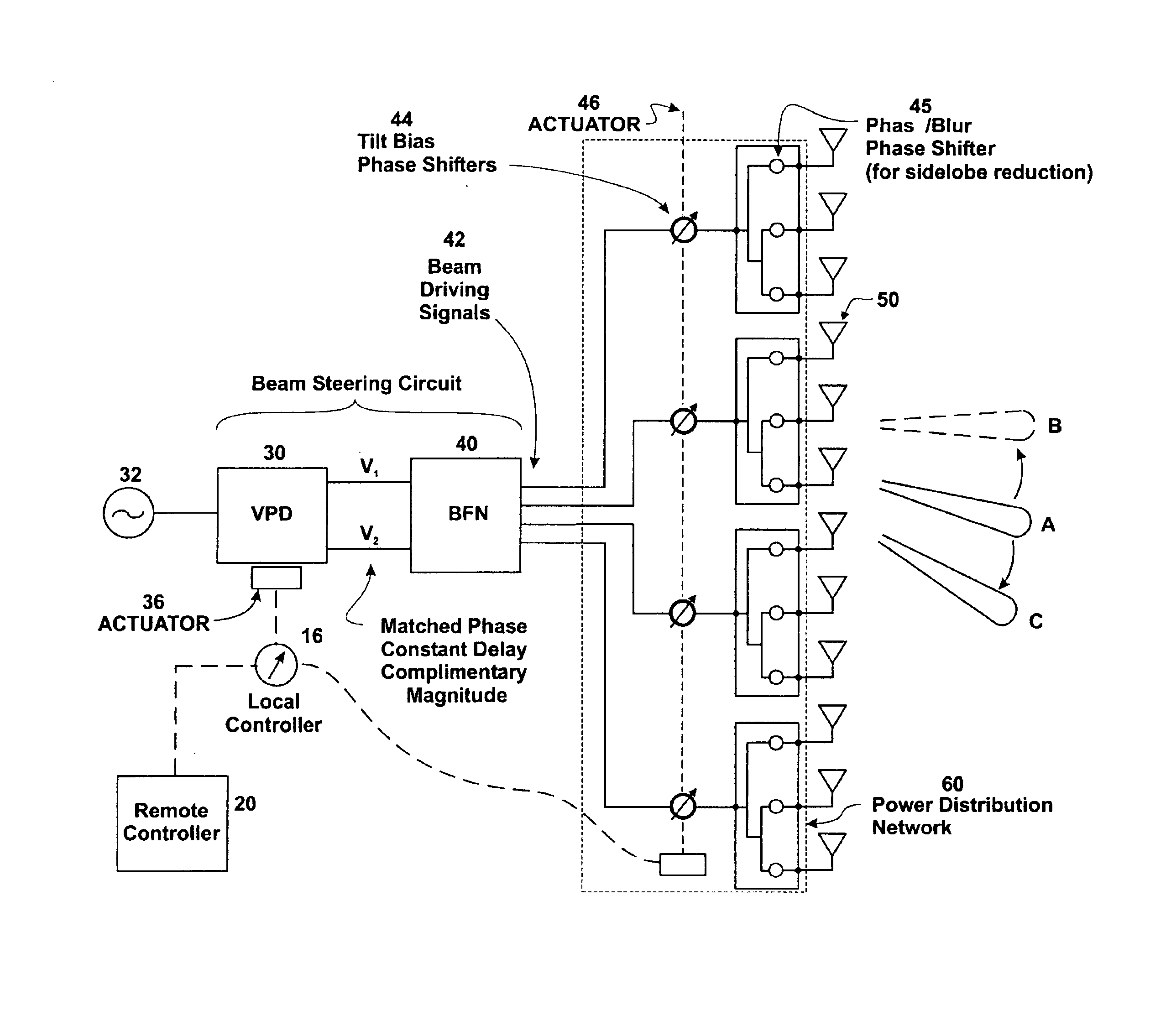
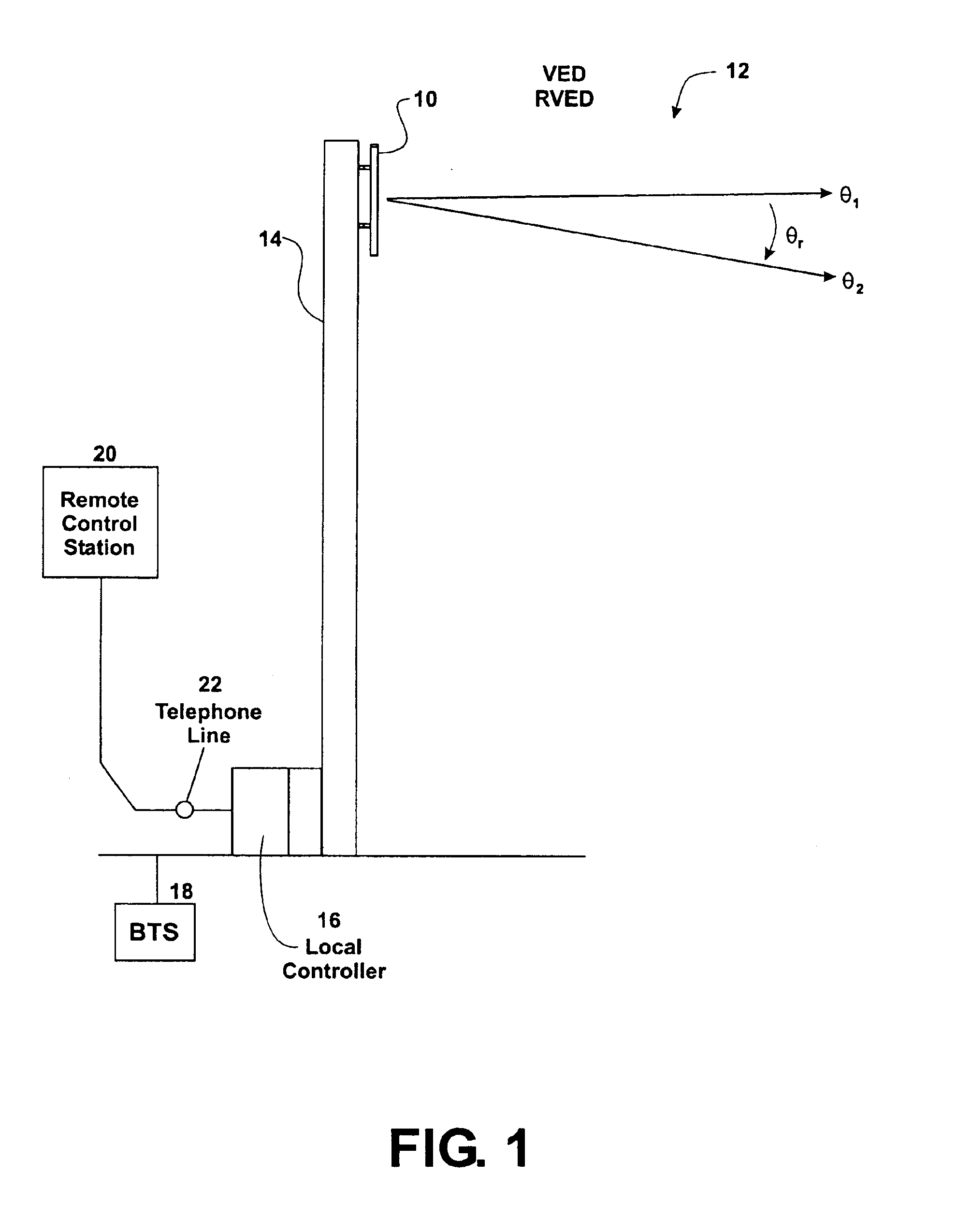
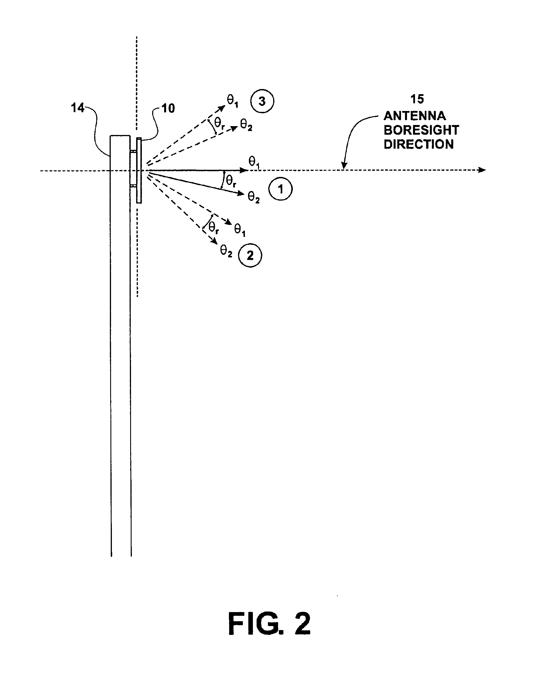
The present invention may be embodied in a number of antenna features for implementing vertical electrical downtilt and sidelobe reduction for wireless base station antenna systems. Although these antenna systems are specifically designed for deployment as wireless base station antennas, the various features of the invention may be used in other applications, such as satellite communication systems, military radar, military communication systems, and any other beam steering application. However, these applications may exhibit different cost and performance considerations that may militate in favor of different, and potentially more sophisticated, beam steering and sidelobe reduction approaches. In addition, many additional antenna features may be implemented in connection with the antenna features described below. However, each of these modifications might add cost and complexity to the system. Therefore, it should also be appreciated that the preferred embodiments described below a...


PUM


Abstract

A dual-polarization wireless base station antenna that implements vertical electrical downtilt and sidelobe reduction using beam steering circuit that includes a variable power divider and a multi-beam beam forming network. The variable power divider includes a single adjustable control element to divide an input voltage signal into a pair of complimentary amplitude voltage drive signals that exhibit matched phase and constant phase delay through the variable power divider. The beam forming network is configured as a double-sided, edge-connected microstrip module mounted to a main panel, which support the antenna elements in a vertical column organized into sub-arrays in a manner that implements sidelobe reduction. The power distribution network connecting the beam steering network to the antenna elements implements beam tilt bias and sidelobe reduction through coordinated phase shifting implemented through transmission media trace length adjustment.

Description

REFERENCE TO RELATED APPLICATIONSThis application incorporated by reference the disclosures of commonly owned U.S. patent application Ser. No. 10 / 290,838 entitled “Variable Power Divider” filed on Nov. 8, 2002; U.S. patent application Ser. No. 10 / 226,641 entitled “Microstrip Phase Shifted” filed on Aug. 23, 2002; and U.S. patent application Ser. No. 10 / 623,382 entitled “Double-Sided, Edge-Mounted Stripline Signal Processing Modules And Modular Network” filed on Jul. 18, 2003.TECHNICAL FIELDThe present invention relates to wireless base station antennas systems and, more particularly, relates to an antenna using a beam steering circuit including a variable power divider and a multi-beam beam forming network to implement vertical electrical downtilt and sidelobe reduction. The antenna, which may be a dual-polarization antenna, may also include a power distribution network that implements beam tilt bias and further sidelobe reduction.BACKGROUND OF THE INVENTIONThe market for wireless b...

Claims


Application Information

Patent Timeline
Patent Type & Authority Patents(United States)
IPC IPC(8): H01Q3/22H01Q3/26H01Q1/24H01Q3/40
CPCH01Q1/246H01Q3/40H01Q3/26H01Q21/00H01Q3/22H01Q23/00H01Q3/02
Inventor RUNYON, DONALD L.CARSON, JAMES CRAWFORDJANOSCHKA, DARIN M.
Owner ARINC
Why Eureka
Try Eureka