Frame synchronizing circuit

a synchronizing circuit and frame technology, applied in the direction of synchronisation signal speed/phase control, instruments, coding, etc., can solve the problems of synchronization circuit, and long time to establish synchronization

Inactive Publication Date: 2005-03-08
FUJITSU LTD
View PDF8 Cites 76 Cited by
  • Summary
  • Abstract
  • Description
  • Claims
  • Application Information

AI Technical Summary

Benefits of technology

When a plurality of patterns similar to the predetermined synchronization pattern are detected in the frame, a plurality of synchronization are carried out by the plurality of frame synchronizing units based on the respective positions of the detected patterns. This provides a large number of candidate positions capable of serving as the position of the first pattern, which reduces the time for the first frame synchronizing unit to complete establishment.

Problems solved by technology

Because of execution of a large number of steps, the frame synchronizing circuit has a problem that it takes long time to establish synchronization again.
This frame synchronization circuit still has a problem that it takes long time until synchronization is established reliably.
Therefore, the frame synchronizing circuit has a problem that it takes long time to re-establish synchronization after it is in the out-of-sync state.

Method used


Image

  • Frame synchronizing circuit
  • Frame synchronizing circuit
  • Frame synchronizing circuit

Examples


Embodiment Construction

A frame synchronizing circuit according to an embodiment of the present invention will be hereinafter described with reference to the accompanying drawings.

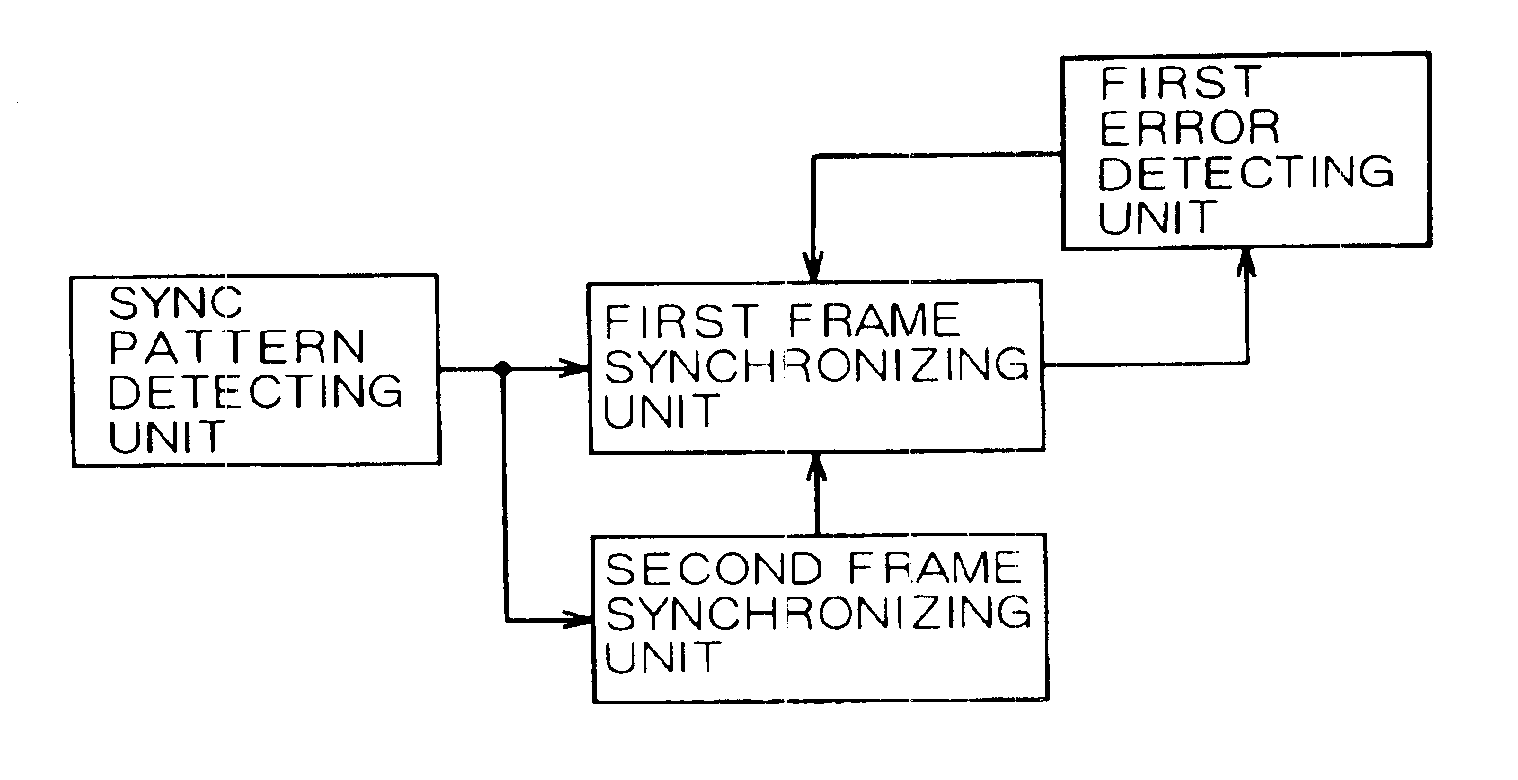
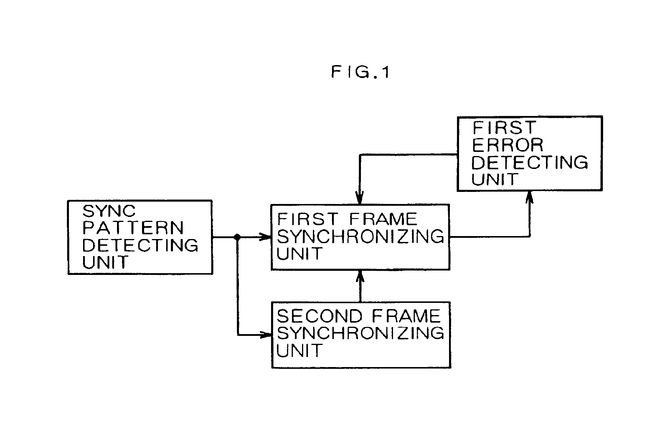
FIG. 1 is a block diagram showing the principle of the invention. As shown in FIG. 1, the frame synchronizing circuit of this invention comprises a sync pattern detecting unit, a first frame synchronizing unit, a second frame synchronizing unit, and a first error detecting unit.

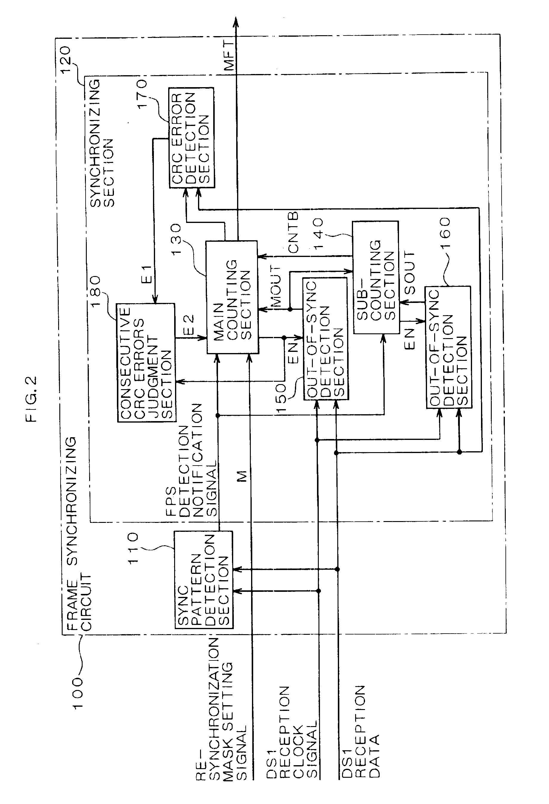
FIG. 2 is a block diagram showing the frame synchronizing circuit according to the embodiment. The frame synchronizing circuit 100 of FIG. 2 incorporates a sync pattern detection section 110 and a synchronizing section 120. The synchronizing section 120 includes a main counting section 130, a sub-counting section 140, two out-of-sync detection sections 150 and 160, a CRC error detection section 170, and a consecutive CRC errors judgment section 180. DS1 reception data and a DS1 reception clock signal that have been extracted from a first-group DS1 signal f...


PUM


Abstract

The frame synchronizing circuit establishes frame synchronization by detecting a sync pattern laid in an incoming frame. The frame synchronization circuit comprises a first frame synchronizing unit and a second frame synchronizing unit. The first and second synchronizing units synchronize with a first pattern, a second pattern at a first position and a second position, respectively. Thereafter, when the first position used for the synchronization by the first frame synchronizing unit is found to be in error, the first frame synchronizing unit synchronizes with the second pattern at the second position used by the second frame synchronization unit.

Description

BACKGROUND OF THE INVENTIONThe present invention relates to a frame synchronizing circuit which establishes frame synchronization by detecting a predetermined sync (synchronization) pattern in a frame or frames.Conventionally, in transmitting digital data by frame, a technique is commonly employed that a sync pattern is incorporated in each frame at a predetermined position and frame synchronization is established on the reception side by detecting it. For example, Japanese Patent Laid-Open Publications Nos. 5-37515, 63-236434, and 6-164572 have disclosed various frame synchronizing circuits in which a main synchronization circuit and an auxiliary synchronization circuit are combined.As disclosed in the above publications, by virtue of the presence of the auxiliary synchronization circuit in addition to the main synchronization circuit, even if the main synchronization circuit is rendered in a pseudo-synchronization state, another synchronization state can be established.In the fram...

Claims


Application Information

Patent Timeline
Patent Type & Authority Patents(United States)
IPC IPC(8): H04L7/00H04L7/08H04J3/06H04L7/04
CPCH04L7/048H04J3/0608
Inventor KAWATAKA, MIYUKI
Owner FUJITSU LTD
Why Eureka
Try Eureka