Fixing device and image forming apparatus

a technology of fixing device and image forming apparatus, which is applied in the direction of electrographic process apparatus, ohmic resistance heating, instruments, etc., can solve the problems of shortening the lifetime of endless belt, and reducing the non-uniformity of fixed image, so as to achieve the reduction of heat transmission between the first roller and the second roller, the lengthening of the endless belt, and the effect of reducing the length

Inactive Publication Date: 2005-03-08
OKI ELECTRIC IND CO LTD
View PDF9 Cites 15 Cited by
  • Summary
  • Abstract
  • Description
  • Claims
  • Application Information

AI Technical Summary

Benefits of technology

With such an arrangement, it is possible to shift the first roller and the endless belt away from the second roller, except when the image is fixed to a recording sheet. Therefore, it is possible to prevent the endless belt from being pressed by the first and second rollers for a long time, so that an impression is not formed on the endless belt. As a result, the lifetime of the endless belt can be lengthened, and the non-uniformity of the fixing image can be reduced. Further, as the second roller has the heat source, it is possible to heat the endless belt and the rollers while the first roller and the endless belt are apart from the second roller. Thus, the heat transmission between the first roller and the second roller can be restricted. Moreover, the temperatures of the endless belt and the rollers can be controlled while the endless belt is moved, with the result that rapid and efficient temperature control can be accomplished.

Problems solved by technology

Such an impression may shorten the lifetime of the endless belt.
Moreover, such an impression may cause a so-called offset phenomenon that a part of the toner image is not fixed to the recording sheet, and may cause a fluctuation of the running speed of the endless belt, which may result in non-uniformity of the fixed image.
Such an impression may be transferred to the endless belt, and may shorten the lifetime of the endless belt.
However, in the conventional fixing device, the pressure roller has no heat source and is heated by the indirect heat transmitted through the endless belt.
However, if the endless belt moves while the endless belt is pressed by the fixing roller and the pressure roller, the endless belt may be damaged by a solidified toner that remains on the endless belt or the pressure roller.
Thus, it is not possible to start moving the endless belt until the solidified toner is molten.
Therefore, it takes a long time to uniformly heat the endless belt and the rollers.
In addition, the temperatures of the endless belt and the rollers affect one another, and therefore the controlling of the temperatures of the endless belt and the rollers is complicated.
As a result, it takes a long time for the endless belt and the rollers to reach the predetermined temperatures.

Method used


Image

  • Fixing device and image forming apparatus
  • Fixing device and image forming apparatus
  • Fixing device and image forming apparatus

Examples


embodiment 1

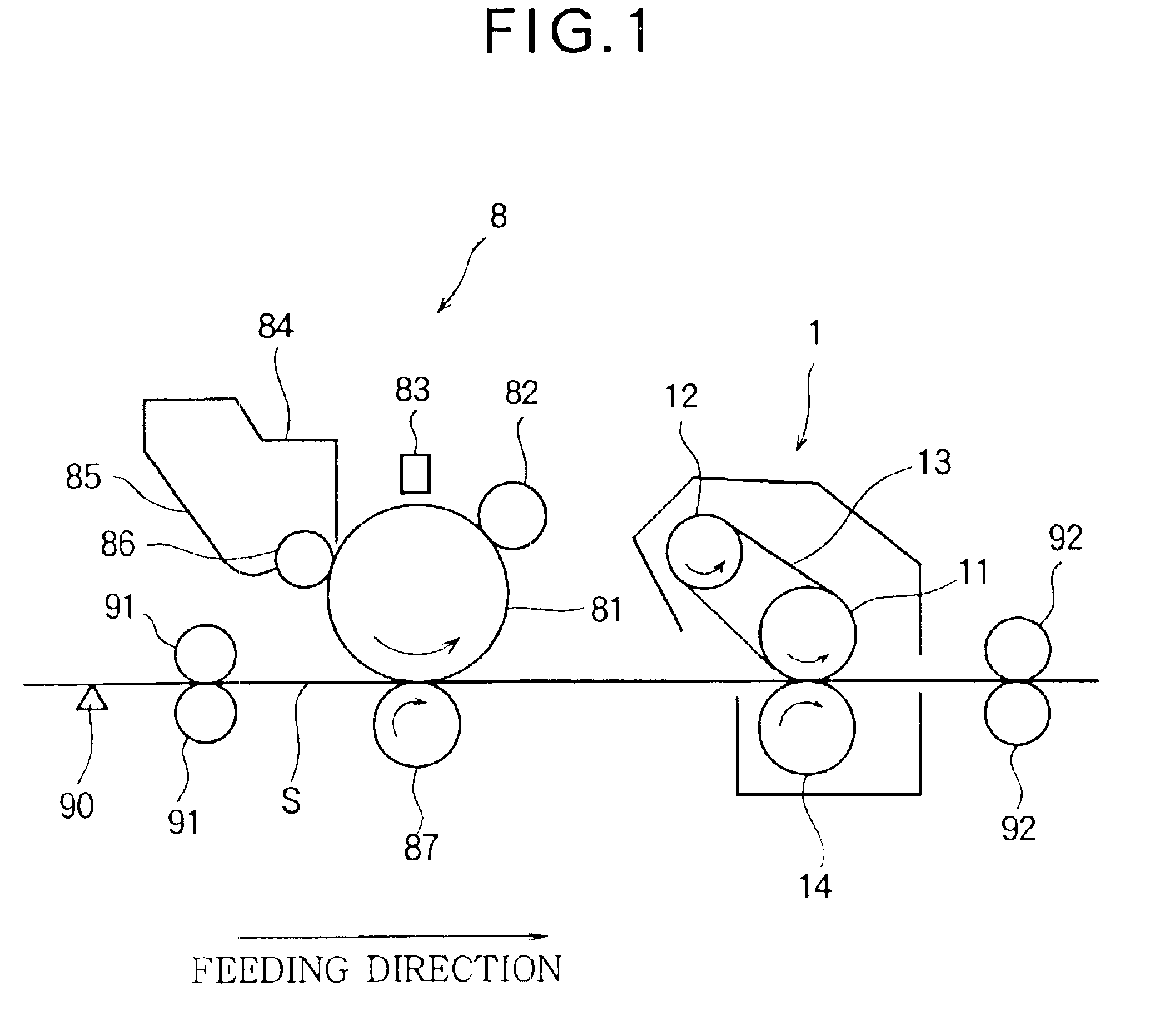
FIG. 1 is a side view illustrating the basic configuration of an image forming apparatus having a fixing device 1 according to Embodiment 1 of the present invention. The image forming apparatus uses an electrophotographic technology, and includes an image forming unit 8 that forms a toner image on a recording sheet S and a fixing device 1 that fixes the toner image (formed by the image forming unit 8) to the recording sheet S. In FIG. 1, the recording sheet S is fed from the left to the right.

The image forming unit 8 includes a photoconductive drum 81 for carrying a latent image. Around the circumference of the photoconductive drum 81, a charging roller 82, an exposing device 83 and a developing device 84 are disposed in this order in the direction of the rotation (counterclockwise in FIG. 1) of the photoconductive drum 81. A transfer roller 87 is disposed at the lower side of the photoconductive drum 81 so that the recording sheet S is pinched by the photoconductive drum 81 and the...

embodiment 2

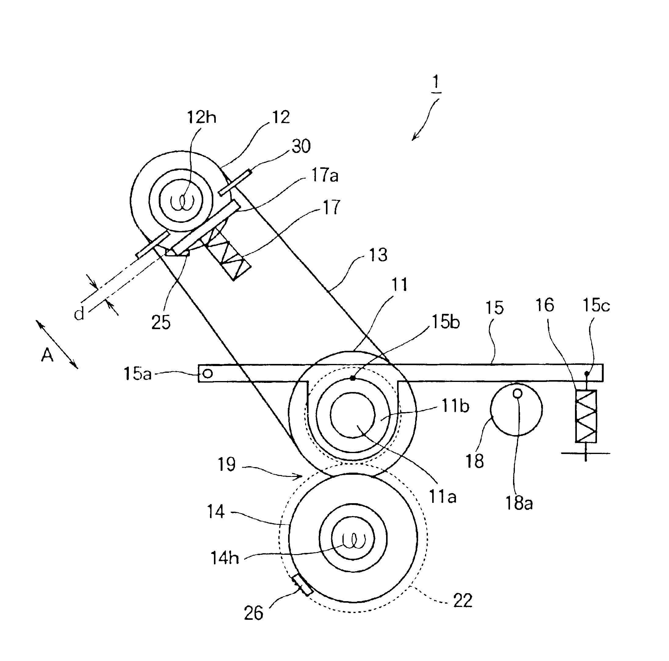
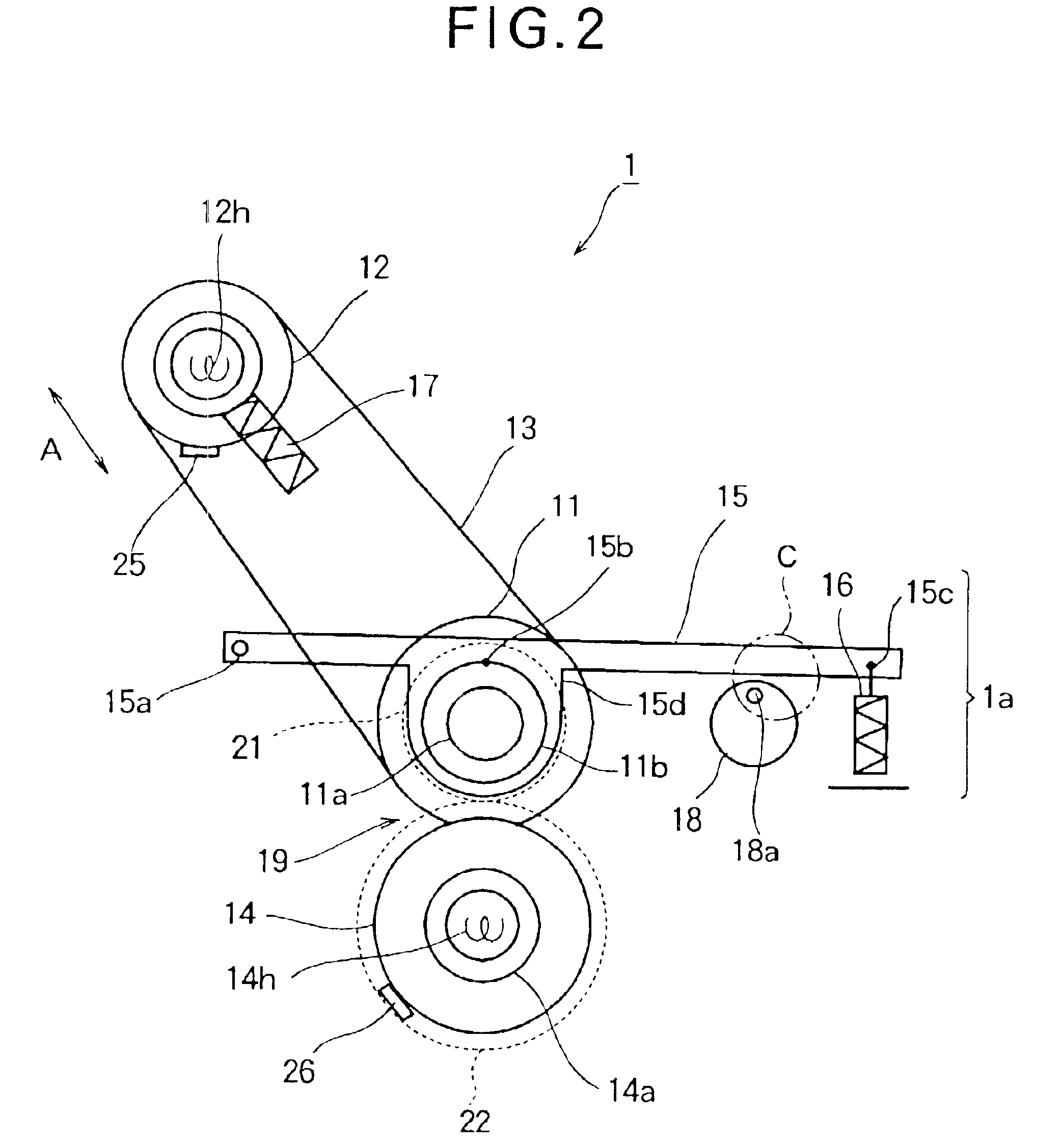
FIGS. 11 and 12 are side views illustrating the structure of the fixing device 1 according to Embodiment 2. FIG. 11 shows the fixing device 1 when the fixing roller 11 is pressed against the pressure roller 14 via the endless belt 13. FIG. 12 shows the fixing device 1 when the fixing roller 11 and the endless belt 13 separate from the pressure roller 14. In Embodiment 2, a mechanism is provided for releasing the tension of the endless belt 13 applied by the tension applying spring 17.

As shown in FIG. 11, a contact member 17a is mounted to the tip of the tension applying spring 17. The contact member 17a abuts against a stopper (i.e., a release mechanism) 30 when the contact member 17a shifts in the direction away from the fixing roller 11. The stopper 30 is fixed to the above described guide member 12d (FIG. 4) that supports the tension applying spring 17. The stopper 30 causes the tension applying spring 17 to stop applying the tension to the endless belt 13, when the fixing roller...

embodiment 3

FIG. 17 is a side view of the fixing device 1 according to Embodiment 3. FIG. 18 illustrates a cam 38 of the fixing device 1 according to Embodiment 3. In Embodiment 3, the fixing roller 11 can have one of two positions at different distances from the pressure roller 14.

The fixing device 1 according to Embodiment 3 has a stopper 30 for restricting the function of the tension applying spring 17, and the position regulating rings 32 (FIG. 14) for preventing the deviation of the endless belt 13, as was described in Embodiment 2. Further, the fixing device 1 has the cam 38 that pushes the swing lever 15 upward. The amount by which the cam 38 pushes the swing lever 15 upward is selectable, so that the fixing roller 11 can have one of two positions at different distances from the pressure roller 14.

The cam 38 is substantially in the form of a disk, and has a rotation center 38a at a position shifted from the center of the disk. As shown in FIG.17, when the circumferential end surface clos...


PUM


Abstract

A fixing device (1) includes a fixing roller (11), a heating roller (12), an endless belt (13) stretched around the fixing roller (11) and the heating roller (12), and a pressure roller (14) facing the fixing roller (11) via the endless belt (13), and has an internal heat source. The endless belt (13) is applied the tension by means of a tension applying spring (17). The fixing roller (11) is supported by a swing lever (15) and pressed against the pressure roller (14). The swing lever (15) is pushed by a cam (18) upward, so that the fixing roller (11) shifts in the direction away from the pressure roller (14). As the fixing roller (11) shifts upward, the tension applied to the endless belt (13) decreases.

Description

BACKGROUND OF THE INVENTIONThis invention relates to a fixing device for fixing a toner image to a recording sheet in a printer or the like, and relates to an image forming apparatus having the fixing device.A fixing device is used to fix a toner image to a recording sheet in an image forming apparatus such as a printer. There is a type of fixing device having an endless belt as disclosed in Laid-Open Patent Publication Nos. 2001-249569 (Page 5, FIG. 1), 2001-194946 (Pages 6-7, FIG. 1) and HEI 7-36306 (Page 4, FIG. 4). Such a fixing device is called a belt-type fixing device.The belt-type fixing device includes a fixing roller such as a rubber covered roller, a heating roller having an internal heat source, and an endless belt stretched around the fixing roller and the heating roller. A pressure roller faces the fixing roller via the endless belt. The pressure roller is pressed against the fixing roller via the endless belt, so that a nip portion is formed between the pressure rolle...

Claims


Application Information

Patent Timeline
Patent Type & Authority Patents(United States)
IPC IPC(8): G03G15/20G03G21/14
CPCG03G15/2032
Inventor MATSUMOTO, KEIGO
Owner OKI ELECTRIC IND CO LTD
Why Eureka
Try Eureka