Device and method of forming a unitary electrically shielded panel

a technology of electrical shielding and device, which is applied in the direction of printed circuit board receptacles, printed circuit board manufacturing, support structure mounting, etc., can solve the problems of increasing the difficulty of designers to control electrical shielding, the bane of electronic equipment and circuit designers, and the emi of emi, so as to achieve less costly manufacturing

Inactive Publication Date: 2005-03-15
LUCENT TECH INC
View PDF2 Cites 23 Cited by
  • Summary
  • Abstract
  • Description
  • Claims
  • Application Information

AI Technical Summary

Benefits of technology

The present invention is less costly to fabricate, requires no additional assembly, and provides a uniform and reliable EMI seal between the electrically shielded panel and the electronic enclosure. In addition, the panel part and gasket are separable and completely recyclable.

Problems solved by technology

Electromagnetic interference (“EMI”) is often the bane of electronic equipment and circuit designers.
The challenge to designers to control EMI becomes increasingly more difficult as the operating speed of electronic devices increases.

Method used


Image

  • Device and method of forming a unitary electrically shielded panel
  • Device and method of forming a unitary electrically shielded panel
  • Device and method of forming a unitary electrically shielded panel

Examples


Embodiment Construction

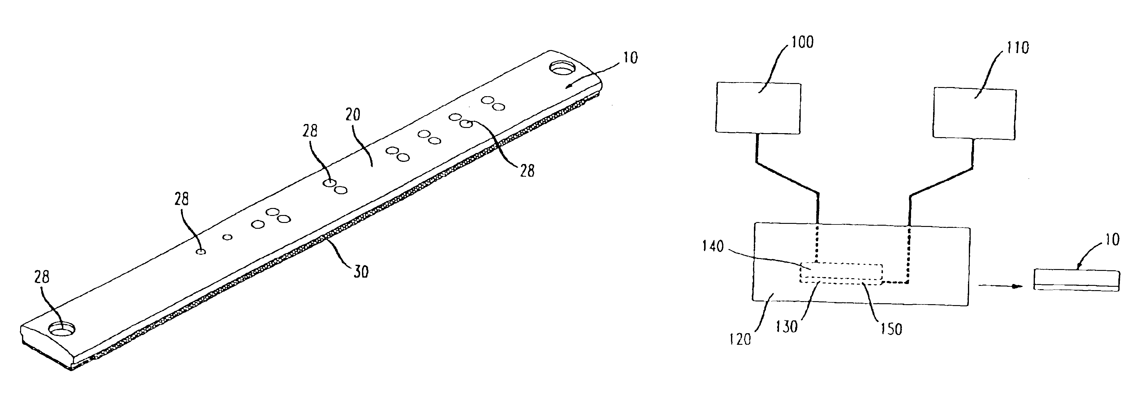
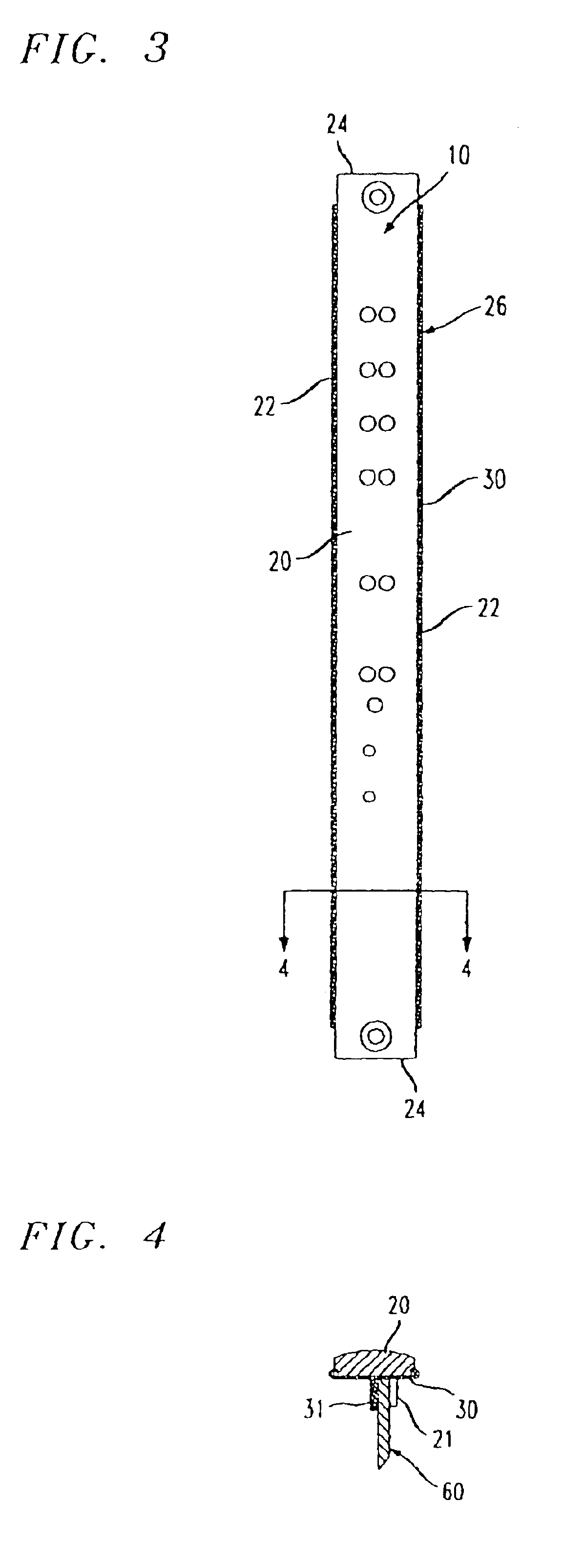
The present invention advantageously provides a novel and unobvious unitarily formed electrically shielded panel that may be used to physically and electromagnetically seal an opening defined in an electronic equipment enclosure to reduce the passage of EMI through the enclosure opening. The present invention also provides a method of forming such a unitary electrically shielded panel. In accordance with the present invention, the unitary shielded panel comprises an electrically non-conductive rigid thermoplastic panel part that is chemically bound to and with a substantially planar, electrically conductive elastomeric shield or gasket, both formed in a single tool or mold during a single injection-molding operation. The terms shield and gasket are used interchangeably herein in describing the substantially planar elastomeric part of the inventive shielded panel.

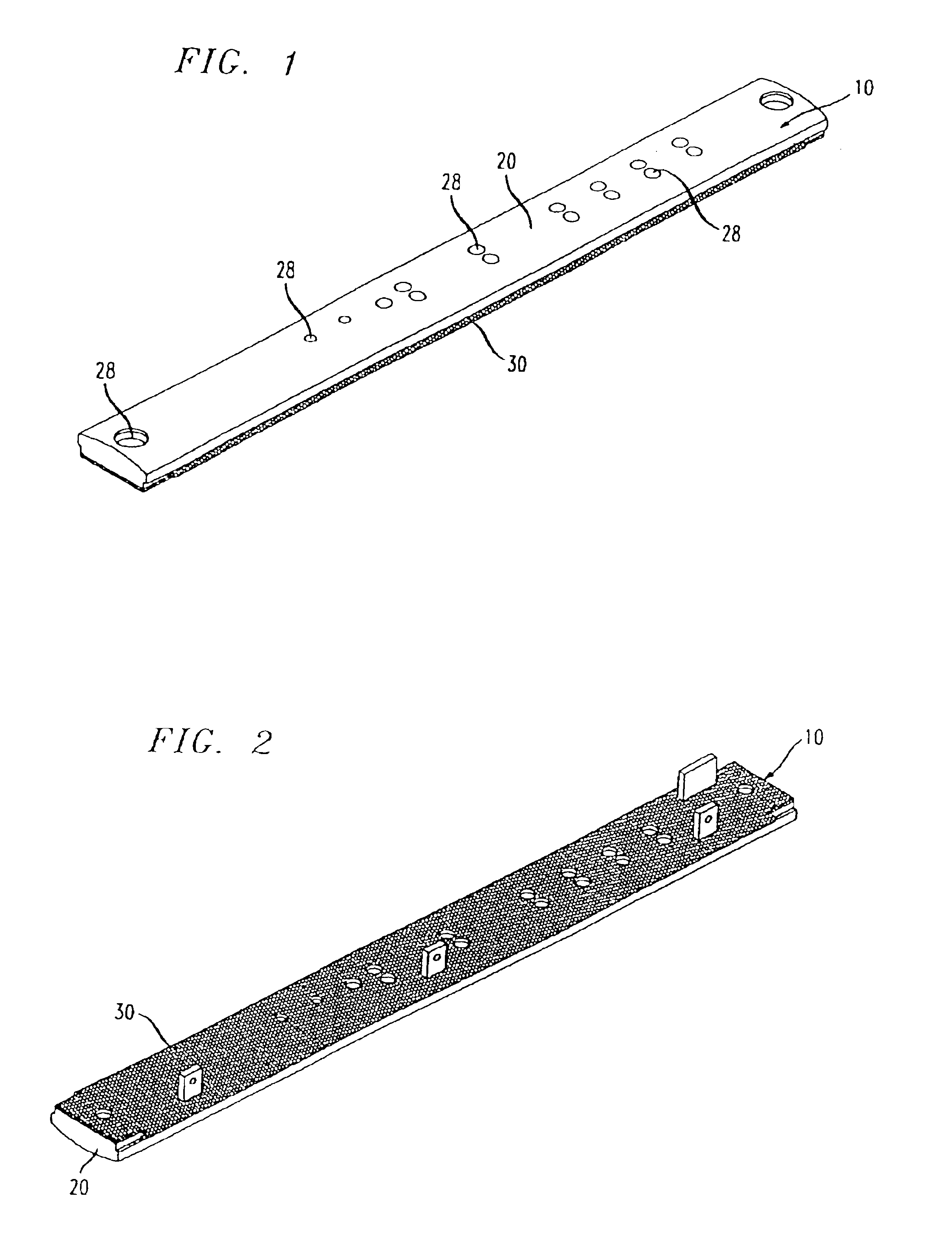
Referring now to the drawings in detail, FIGS. 1 and 2 depict an electrically shielded panel 10 constructed in accordance ...


PUM


Abstract

A device and method of unitarily forming an electrically shielded panel for use in electromagnetically sealing an opening defined in an electronic enclosure. The unitary electrically shielded panel is formed of an electrically non-conductive rigid thermoplastic panel part and a substantially planar, electrically conductive elastomeric gasket bonded together to form the unitary panel in a single tool during a single injection-molding operation.

Description

BACKGROUND OF THE INVENTION1. Field of the InventionThe present invention relates to electronic enclosure sealing devices and, more particularly, to a device and method of forming a unitary electrically shielded panel.2. Description of the Related ArtElectromagnetic interference (“EMI”) is often the bane of electronic equipment and circuit designers. Federal regulations mandate that electronic equipment enclosures must not radiate electromagnetic signals that interfere with other proximately located electronic equipment. Electronic equipment enclosures must also be sufficiently shielded against interference from electromagnetic signals radiated from other proximately located equipment. The challenge to designers to control EMI becomes increasingly more difficult as the operating speed of electronic devices increases.Currently, apertures defined in electronic equipment enclosures are sealed using electrically shielded panels, e.g. circuit-pack faceplates, blank filler panels, covers,...

Claims


Application Information

Patent Timeline
Patent Type & Authority Patents(United States)
IPC IPC(8): H05K9/00H05K7/14
CPCH05K7/1425H05K9/0015Y10T29/49144Y10T29/49158Y10T29/49146
Inventor DISPENZA, JOHN A.THAKAR, DIPAK
Owner LUCENT TECH INC
Why Eureka
Try Eureka