Shift lever device

a technology of shifting lever and lever body, which is applied in the direction of mechanical control devices, manual control with single controlling member, instruments, etc., can solve the problems of difficult to provide the device with a robust construction and failed to exhibit a satisfied performance of the shifting lever device of the publication, and achieve the effect of robust construction

Inactive Publication Date: 2005-03-15
FUJI KIKO CO LTD
View PDF5 Cites 25 Cited by
  • Summary
  • Abstract
  • Description
  • Claims
  • Application Information

AI Technical Summary

Benefits of technology

According to the present invention, there is provided a shift lever device of gate type, having a shift inhibiting mechanism by which, when operated, unwilled N→R shifting and / or P→R shifting of a shift lever is assuredly suppressed.
According to the present invention, there is provided a shift lever device of gate type, which is robust in construction.

Problems solved by technology

However, due to its inherent construction, even the shift lever device of the publication has failed to exhibit a satisfied performance.
That is, it is difficult to provide the device with a robust construction.

Method used


Image

  • Shift lever device
  • Shift lever device
  • Shift lever device

Examples


Embodiment Construction

In the following, the present invention will be described in detail with reference to the accompanying drawings.

For ease of understanding, various directional terms, such as, right, left, upper, lower, rightward, etc., are included in the description. However, such terms are to be understood with respect to only a drawing or drawings on which the corresponding part or portion is shown.

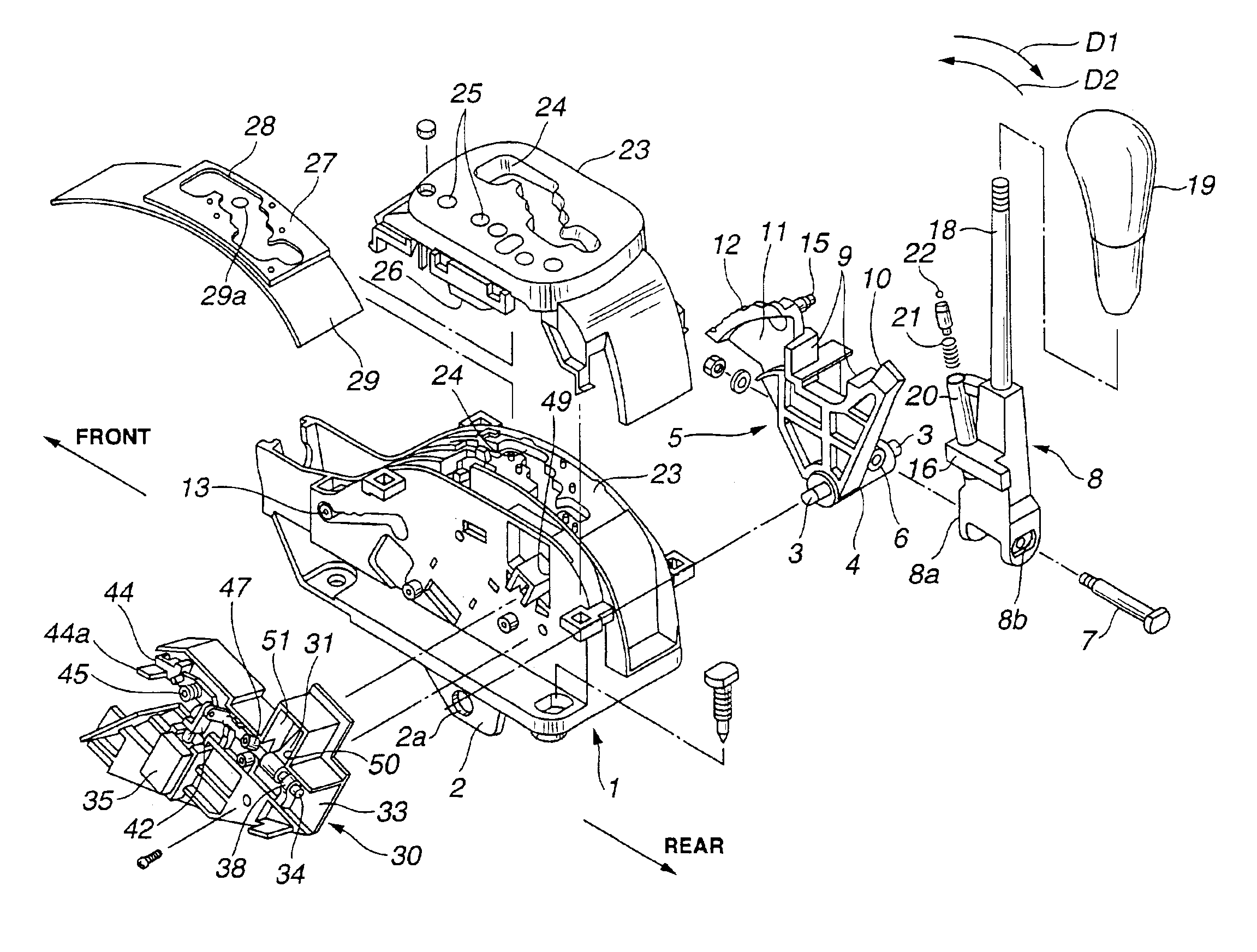
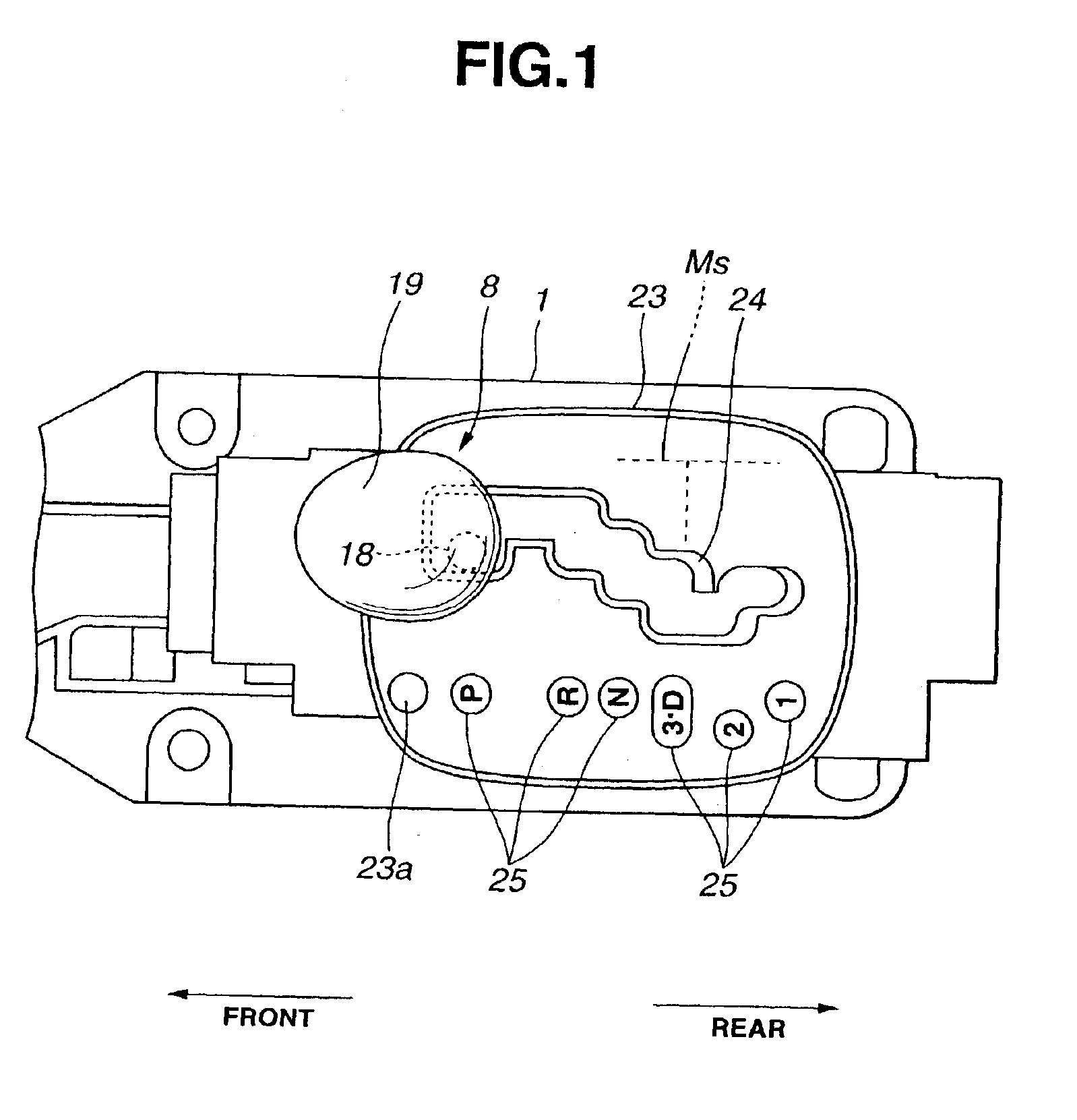
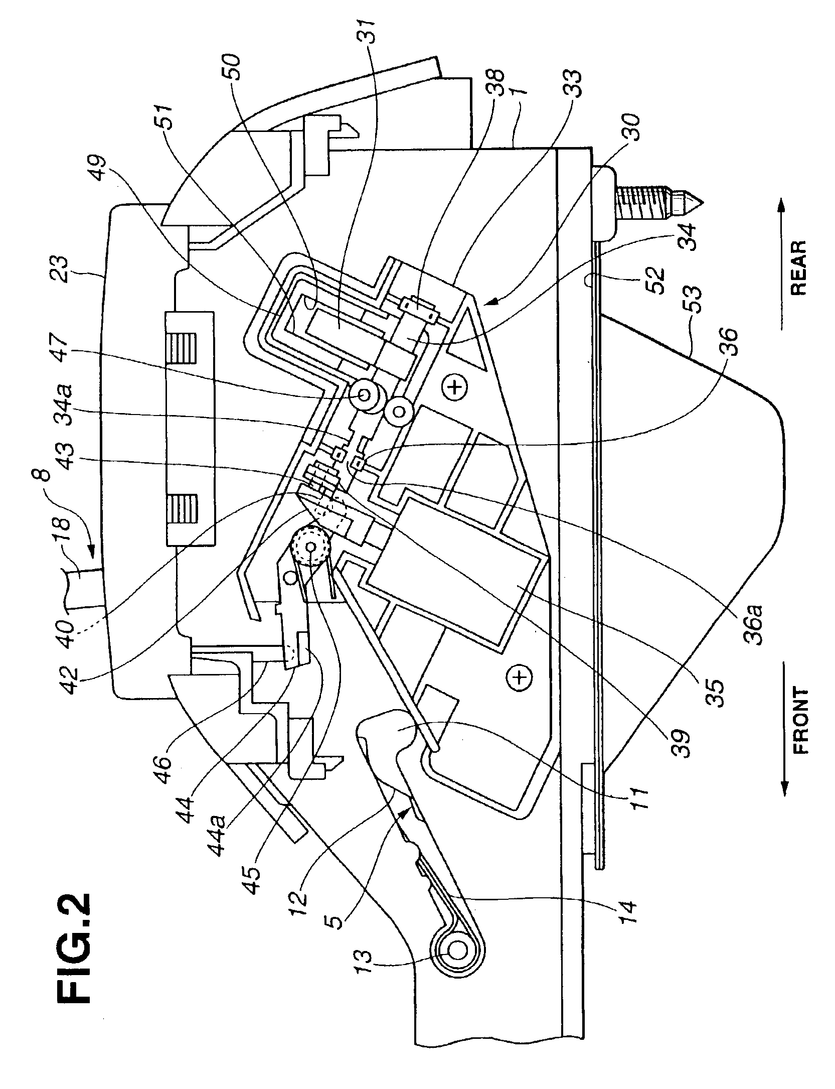
Referring to the drawings, particularly FIG. 5, there is shown a shift lever device of the present invention.

Denoted by numeral 1 is a case made of a reinforced plastic, which is tightly mounted on a given portion of a vehicle body. The case 1 is formed at a bottom thereof with two parallel brackets 2 each extending in a fore-and-aft direction of the vehicle body. The brackets 2 are formed with respective circular openings 2a which are aligned. The aligned circular openings 2a rotatably receive therein axially opposed ends 3 of a shaft 4 of a select member 5. Thus, the select member 5 pivots forward an...


PUM


Abstract

A select member has a stopper arm, is pivotally connected to a case and is pivotal about a first axis substantially perpendicular to a longitudinal axis of the case. A shift lever is connected to the select member and pivotal about a second axis substantially in parallel with the longitudinal axis and has a portion that passes through a gate slot. A lock lever is pivotal into the window to block gthe stopper arm. An actuating mechanism permits the lock lever to selectively assume a position wherein the lock lever blocks movement of the stopper arm.

Description

BACKGROUND OF THE INVENTION1. Field of the InventionThe present invention relates in general to shift lever devices of an automotive automatic transmission, and more particularly to the shift lever devices of a type that provides P-position with a lock function and N-position with a R-position shift inhibiting function.2. Description of the Related ArtHitherto, in automotive automatic transmissions, there have been proposed various types of shift lever devices. One of them is of a so-called gate type wherein a shift lever is permitted to move along a zigzag path for selecting a desired gear position. In order to suppress unwilled shifting of the shift lever, for example, unwilled movement from N-position to R-position of the shift lever, the shift lever devices of such gate type have a shift inhibiting mechanism. One of them is disclosed in Laid-open Japanese Patent Application (Tokkaihei) 11-151946. The shift inhibiting mechanism of this publication employs a lock lever that is arr...

Claims


Application Information

Patent Timeline
Patent Type & Authority Patents(United States)
IPC IPC(8): F16H59/10F16H61/22B60K20/02
CPCF16H59/10F16H61/22Y10T74/2011Y10T74/20098Y10T74/20067Y10T74/20085B60K20/02
Inventor SHIOJI, NORIHITONARAZAKI, MITSUO
Owner FUJI KIKO CO LTD
Why Eureka
Try Eureka