Labeled drill pipe

a drill pipe and label technology, applied in the field can solve the problems of long service life of labeled drill pipe, and achieve the effects of long service life, long service life and robust construction

Inactive Publication Date: 2011-12-29
COLEMAN JAY B
View PDF5 Cites 14 Cited by
  • Summary
  • Abstract
  • Description
  • Claims
  • Application Information

AI Technical Summary

Benefits of technology

[0009]It is a further object of the invention to provide a drill pipe with a label that is likely to last for the life of the drill pipe. The label cannot fall off of the drill pipe and is positioned in such a way as to minimize wear and degradation thereof. The label can comprise: a trademark, a logo, a serial number, an alphanumeric code, and any other sort of indicia identifying the source of the drill pipe or quality of the drill pipe.
[0010]It is another object of the invention to provide a labeled drill pipe of the type described that is undamaged by the labeling process thus retaining its inherent corrosion-resistance, strength and durability. Thus, the labeled drill pipe is expected to have a lengthy service life.
[0011]It is an object of the invention to provide improved features and arrangements thereof in a labeled drill pipe for the purposes described that is robust in construction, reasonably inexpensive to manufacture, and fully dependable in use.

Problems solved by technology

Thus, the labeled drill pipe is expected to have a lengthy service life.

Method used


Image

  • Labeled drill pipe
  • Labeled drill pipe
  • Labeled drill pipe

Examples


Embodiment Construction

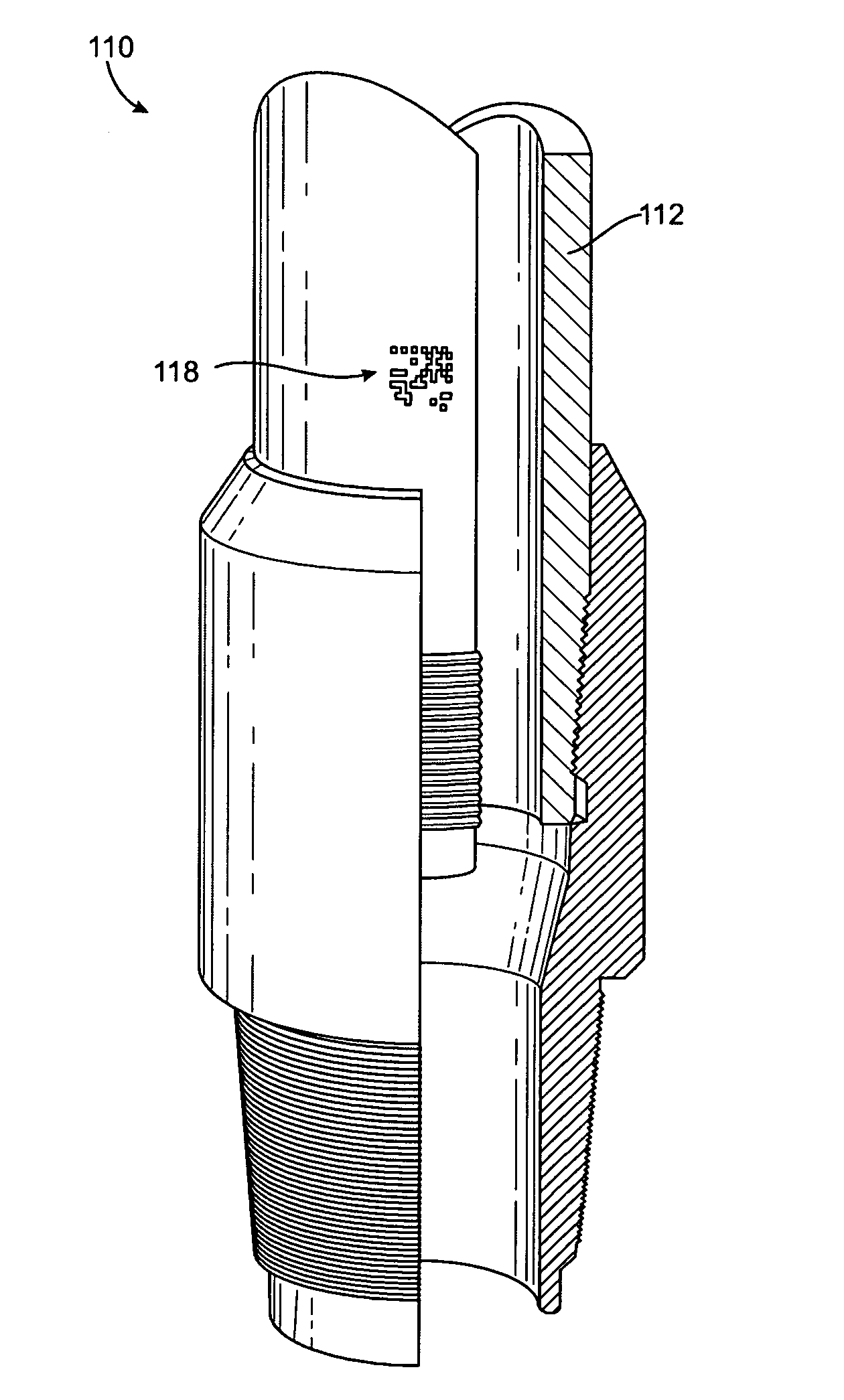
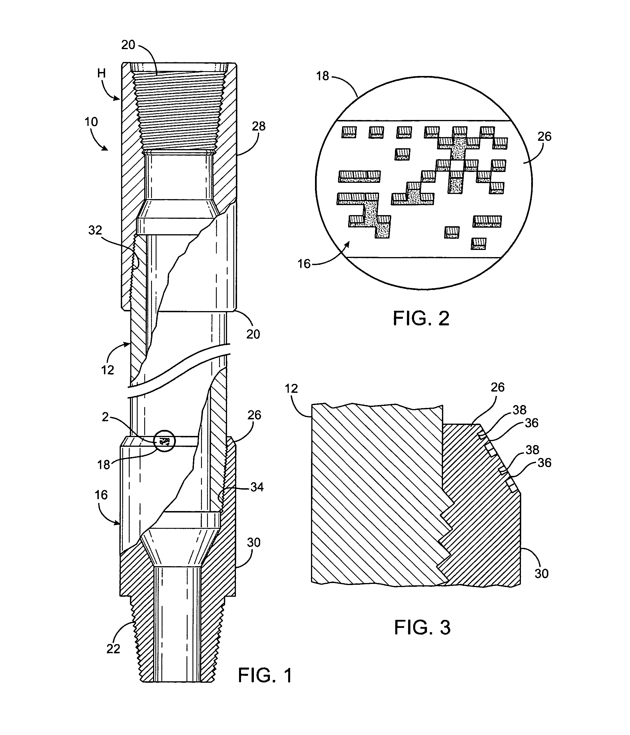
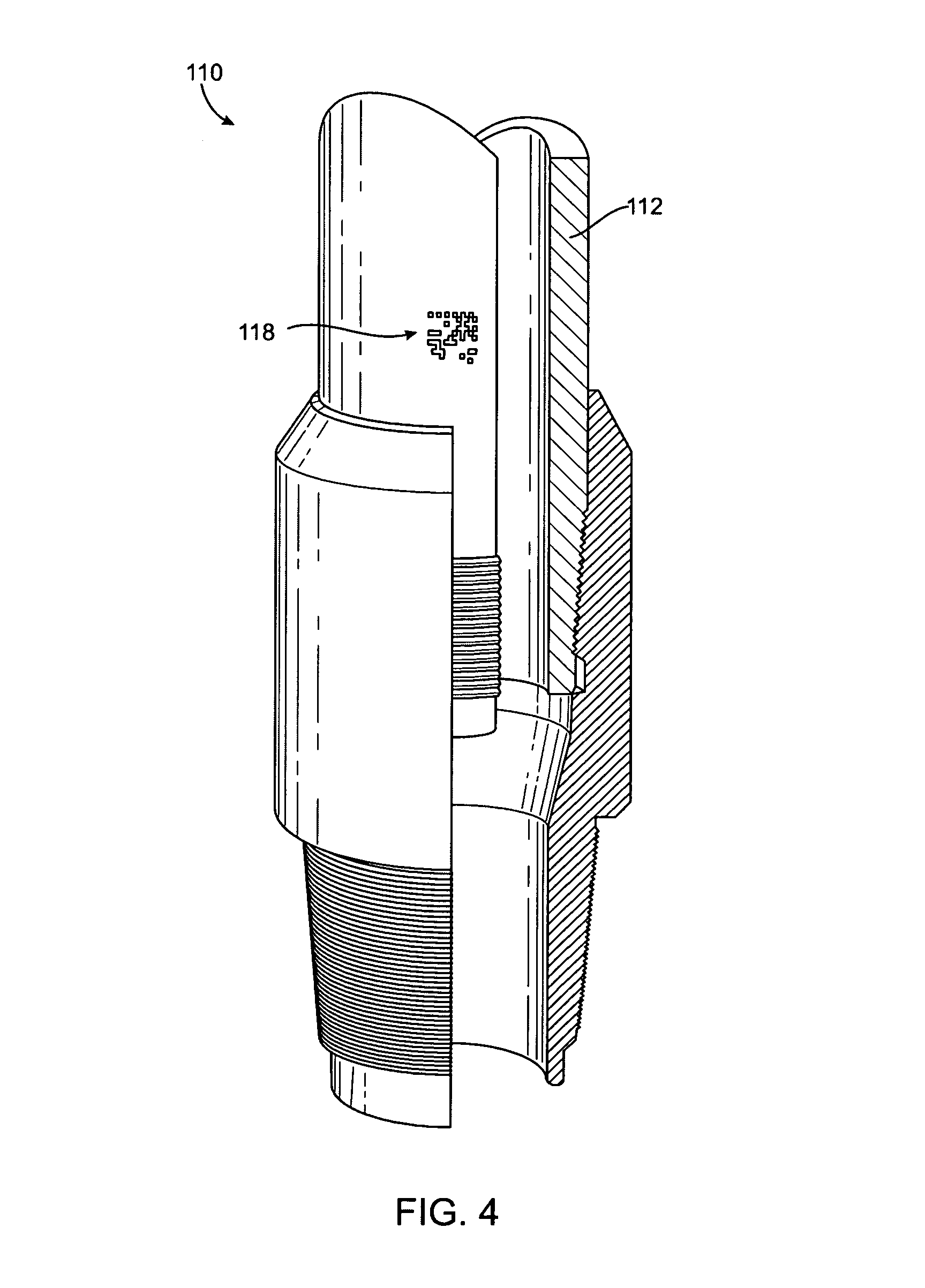
[0020]Referring now to the FIGS., a drill pipe constructed in accordance with my invention is shown at 10. The drill pipe 10 is a hollow, cylindrical, seamless tube 12 having a pair of connectors or tool joints 14 and 16 affixed to its opposite ends. The drill pipe 10 is labeled with a bar code 18 applied to the tool joint 16. The bar code 18 is unique to the drill pipe 10 and is used to identify the drill pipe 10 throughout its life.

[0021]The tube 12, and hence the drill pipe 10, is specified by its outside diameter, weight per foot, steel grade, and length. These parameters are a matter of design choice (and can vary widely), but are usually selected for an optimum combination of strength, hardness, and fatigue resistance. The American Petroleum Institute (API) has adopted standards meant to reinforce safe drilling practices by setting these parameters within fixed ranges. The tube 12 would normally be configured to meet API standards.

[0022]In selecting a tube 12 of appropriate si...


PUM


Abstract

A drill pipe including a tube having opposite ends. An internally threaded connector is provided at one of the opposite ends of the tube. An externally threaded connector is provided at the other one of the opposite ends of the tube. The externally threaded connector is adapted to mate with the internally threaded connector on a second drill pipe. A bar code is etched into either the tube, the internally threaded connector, or the externally threaded connector.

Description

FIELD OF THE INVENTION[0001]The present invention relates generally to card, picture, and sign exhibiting and, more particularly, to checks, labels and tags carried on cylindrical objects.BACKGROUND OF THE INVENTION[0002]Rotary drilling is the act of making a hole in the earth through which hydrocarbons can be produced if encountered in commercial quantities. During rotary drilling, a weighted bit is fastened to, and rotated by, a drill string, comprising drill pipe and drill collars, with new sections or joints being added as drilling progresses. The cuttings are lifted from the hole by a drilling fluid which is pumped down the inside of the drill string, through nozzles in the bit, and upward through the annular space between the drill string and the wall of the hole. At the surface, the returning drilling fluid is passed through a series of tanks or pits within which cuttings are separated and fluid treatments are accomplished. The drilling fluid is drawn from the last of the pit...

Claims


Application Information

Patent Timeline
Patent Type & Authority Applications(United States)
IPC IPC(8): E21B17/00
CPCE21B17/006
Inventor COLEMAN, JAY B.
Owner COLEMAN JAY B
Why Eureka
Try Eureka