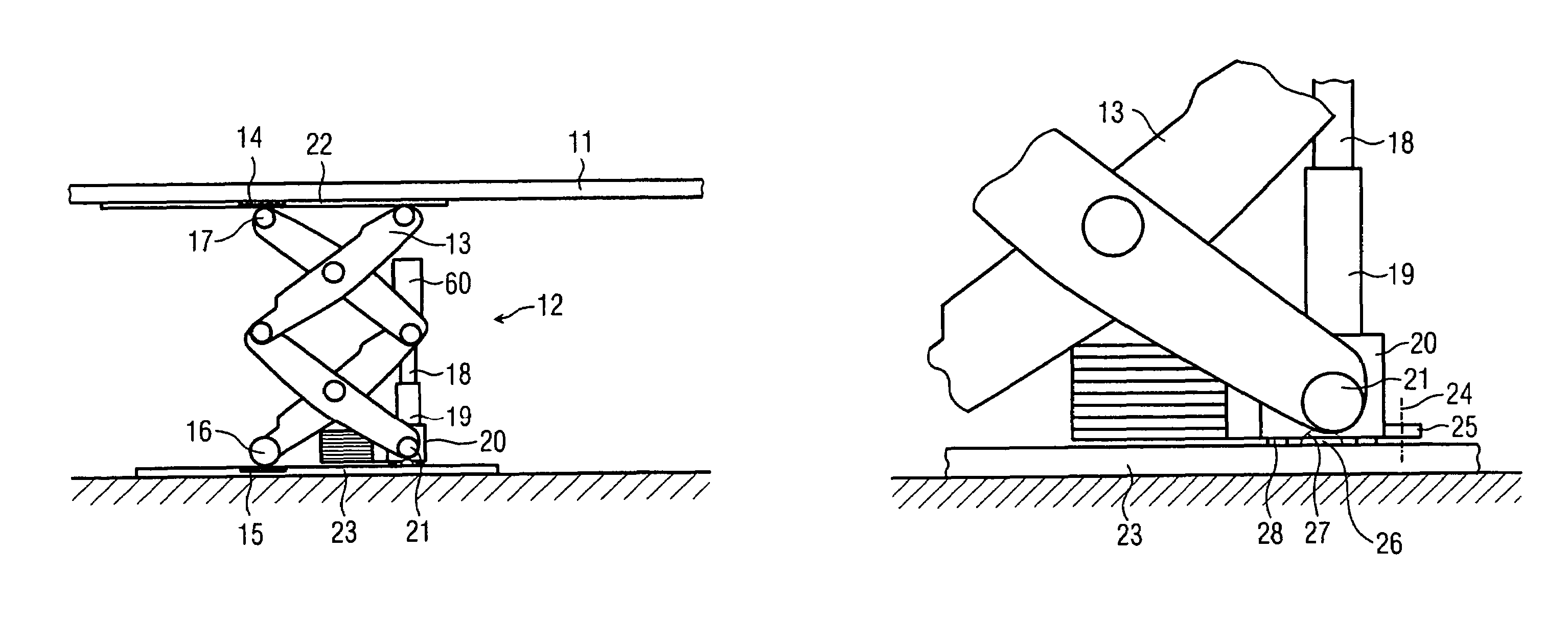
Lifting unit

a technology of lifting unit and supporting foot, which is applied in the direction of patient positioning for diagnostics, instruments, applications, etc., can solve the problems of not being able to produce every desired spatial configuration of patient and device, affecting the torque on the supporting foot, and unable to position this massive mechanical structure in three dimensions, so as to prevent the exertion of torque, reduce wear and friction in the spindle drive, and be free from design complication

Inactive Publication Date: 2009-06-09
SIEMENS HEALTHCARE GMBH
View PDF24 Cites 7 Cited by
  • Summary
  • Abstract
  • Description
  • Claims
  • Application Information

AI Technical Summary

Benefits of technology

[0014]In one embodiment, the spindle drive is supported in a ball joint both on a base plate of the DT device and in the component to be driven. The spindle drive is rotated about the center of rotation of the respective ball joint. For example, in one embodiment, the component driven by the spindle drive is loaded eccentrically with reference to the spindle drive. In this embodiment, a torque is exerted on the spindle drive that varies the alignment of the spindle drive, but the spindle drive follows the deflection by rotating about the respective ball joint and thus maintains the proper alignment between the spindle and the spindle nut. Maintaining the alignment prevents or at least minimizes an increase in wear and friction owing to eccentric loading of the component.
[0015]In one embodiment, at least one of the ball joints is aligned with the spindle nut of the spindle drive. For example, the load of the component to be driven, which rests on the spindle, is centrally led via the spindle into the ball joint, which minimizes friction and wear inside the ball joint. The ball joint is optimally mobile and effectively compensates for alignment errors in the spindle drive.
[0017]In one embodiment, the fixed bearing and the alignment of the spindle define a common plane. This common plane enables the spindle drive and scissors movement to cooperate in a manner that is free from friction.
[0018]In one embodiment, the center of rotation of the ball joint lies on an axis running through the fixed bearing of the double scissor mechanism. The eccentric loading of the patient support may lead to a deflection of the double scissor mechanism about the fixed bearing, for example, in the form of a rotation. The common axis of the fixed bearings and the ball joint allows the spindle drive to be deflected about the same axis of rotation. Accordingly, alignment errors in the spindle drive due to eccentric loading of the patient support may be minimized or prevented.
[0020]In another embodiment, the drive unit is elastically supported on the base plate together with the spindle, for example on rubber buffers. The elastic bearing supports the weight of the drive unit, for example, when the drive mass is not arranged with rotational symmetry about the center of rotation of the ball joint. Conventionally, the mass of an eccentric arrangement of the drive unit exerts a torque on the spindle. The elastic bearing of the drive unit prevents the exertion of the torque on the spindle. In one exemplary embodiment, the elastic bearings are suitably moved to enable a (slight) rotation about the ball joint, and thus the spindle movements that maintain the spindle alignment remain possible. The suppression of a torque exerted on the spindle by the drive unit acts to reduce wear and friction in the spindle drive.

Problems solved by technology

The ability to position this massive mechanical structure in three dimensions is limited by the size of the structure.
However, because of the generally restricted positioning ability, not every desired spatial configuration of patient and device can be produced.
The torque on the supporting foot is adversely affected when a patient is not positioned centrally over the supporting foot.
If the patient support is displaced horizontally, this torque increases because the lever is longer.
This loading creates alignment errors in drive components that must be aligned vertically.
However, spindle drives are vulnerable to the described problem of alignment errors.
Similar problems arise when positioning devices other than patient support tables.
The considerable weight of the C-arc and the holder, which is typically on the side of the support, creates torques that deflects the vertical drive and the horizontal drive out of alignment.
However, this increases both friction and wear between the spindle and the spindle nut.

Method used


Image

  • Lifting unit
  • Lifting unit
  • Lifting unit

Examples


Embodiment Construction

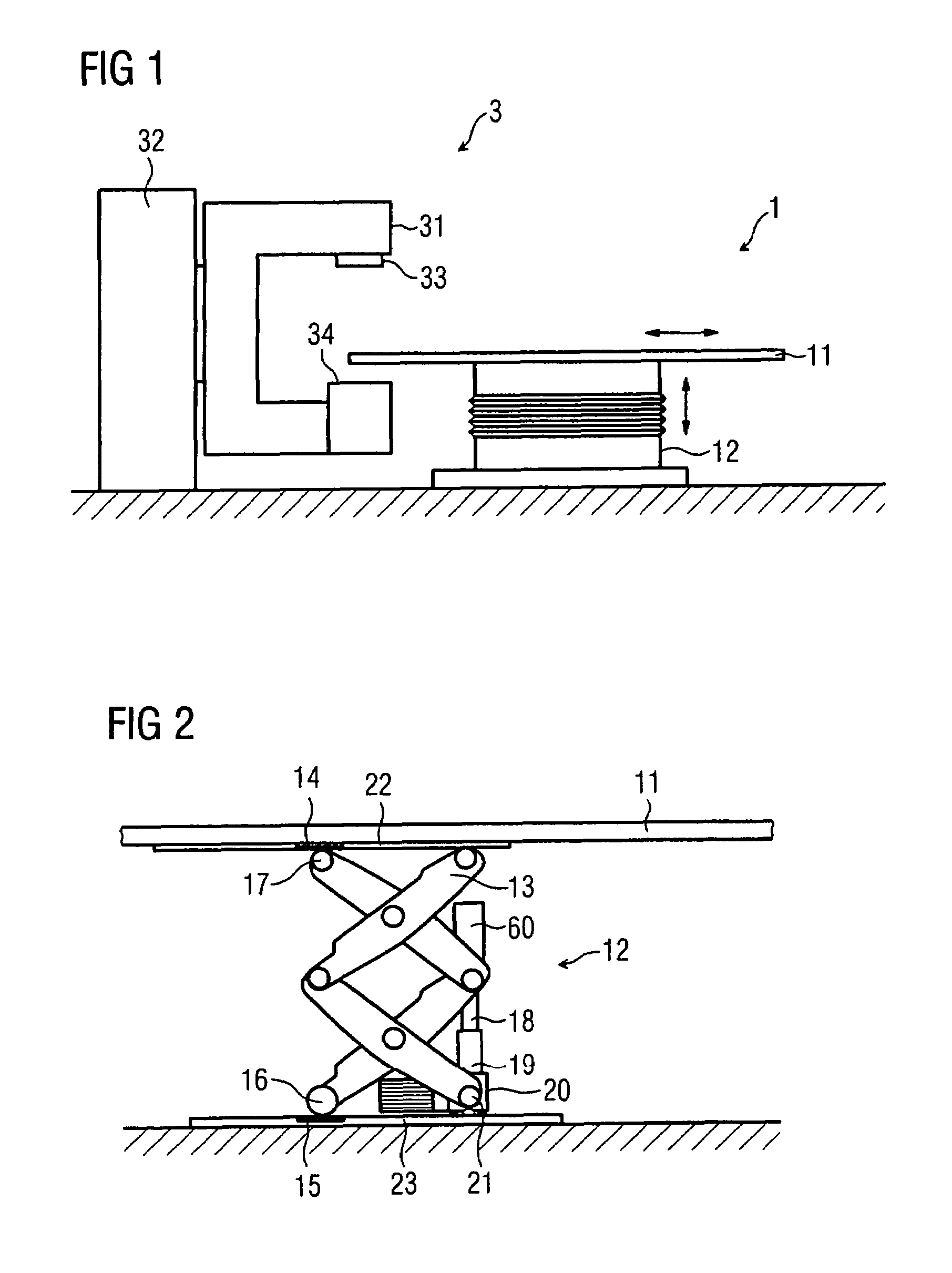
[0029]In one embodiment, as shown in FIG. 1, a diagnostic and / or therapeutic device (DT device) 3 includes a patient support apparatus 1 and a C-arc 31 that carries an X-ray emitter 33 and an X-ray detector 34. For example, the C-arc can be used to generate X-ray images having X-radiation with low energies or therapeutic irradiation having X-radiation with high energies. The C-arc 31 is supported by a C-arc pedestal 32. The C-arc pedestal 32, as shown in FIG. 1, is a structure that is supported by the floor of a room. In alternate embodiments, the C-arc pedestal 32 is supported by the wall or ceiling of the room. The C-arc 31, which positions the X-ray emitter 33 and the X-ray detector 34, and the patient support apparatus 1 are positioned so that a patient is detected by the X-ray beam. In one exemplary embodiment, the C-arc 31 is rotated about at least one horizontal axis (not illustrated) and is moved (not illustrated) vertically in the C-arc pedestal 32.

[0030]The patient support...


PUM


Abstract

A medical lifting device is provided. The medical lifting device comprises a lifting unit that is operable in a linear motion. A spindle drive is operable to adjust the lifting unit. A first ball joint is disposed in the lifting unit and a second ball joint is disposed where the spindle drive is respectively supported.

Description

[0001]The present patent document claims the benefit of the filing date of DE 10 2005 048 392.5, filed Oct. 10, 2005.BACKGROUND[0002]1. Field[0003]The present embodiments relate to a lifting unit and to a patient support device.[0004]2. Related Art[0005]Medical diagnostics and therapy devices generally include a lifting or telescopic apparatus that adjusts equipment components. Equipment components that are commonly adjusted are, for example, X-ray emitters, X-ray detectors, object tables in mammography, C-arcs, operating tables or patient support apparatuses for C-arcs, computer tomography equipment, magnetic resonance equipment or nuclear medicine and radiation therapy equipment. Radiation, electromagnetic waves or sound waves can be used to examine or treat patients in such devices. For example, X-, electron, or particle rays, ultrasonic waves or magnetic fields can be used for treatment. Generally, the devices include relatively heavy (massive) radiation or active sources and he...

Claims


Application Information

Patent Timeline
Patent Type & Authority Patents(United States)
IPC IPC(8): A61B6/04
CPCA61B6/0457A61G13/06A61B6/4441A61B6/0487
Inventor HOTH, TOBIASWEIDNER, PAUL
Owner SIEMENS HEALTHCARE GMBH
Why Eureka
Try Eureka