Network relay device and control method thereof

a network relay and relay technology, applied in data switching networks, frequency-division multiplexes, instruments, etc., to achieve the effect of reducing false detection of failures

Inactive Publication Date: 2013-01-17
ALAXALA NETWORKS
View PDF2 Cites 11 Cited by
  • Summary
  • Abstract
  • Description
  • Claims
  • Application Information

AI Technical Summary

Benefits of technology

[0010]Consequently, there is a need to prevent or at least reduce false detection of a failure in a virtual line by a network relay device configured to use a virtual line for making physical lines redundant and to exchange control frames for use in checking the status of a network with another network relay device.
[0012]In the network relay device of this aspect, the status check frame controller changes the frame-sending port to be used to send a next status check frame, in order to avoid continuously using the same port as both the frame-sending port to send the status check frame for use in checking the status of a network, which the network relay device is connected with via the virtual line, and the frame-receiving port to receive the status check frame from another network relay device. This configuration effectively prevents the status check frames from being undesirably discarded on the occurrence of a failure in a physical line connected with the frame-sending, frame-receiving port, in the state where the same port is continuously used as both the frame-sending port and the frame-receiving port of the status check frames. As a result, this configuration prevents or at least reduces false detection of a failure in the virtual line by the network relay device configured to use the virtual line for making physical lines redundant and to exchange control frames or status check frames for use in checking the status of the network with another network relay device.

Problems solved by technology

This problem is not characteristic of the concrete protocols or their combinations, such as STP, Ring protocol or Link Aggregation but is commonly found in any network relay device configured to make physical lines redundant and exchange control frames (or packets) for use in checking the status of the network with another network relay device.

Method used


Image

  • Network relay device and control method thereof
  • Network relay device and control method thereof
  • Network relay device and control method thereof

Examples


first embodiment

B. First Embodiment

[0098](B-1) System Configuration

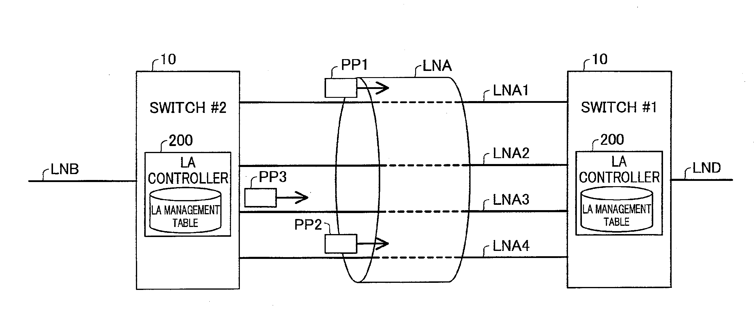
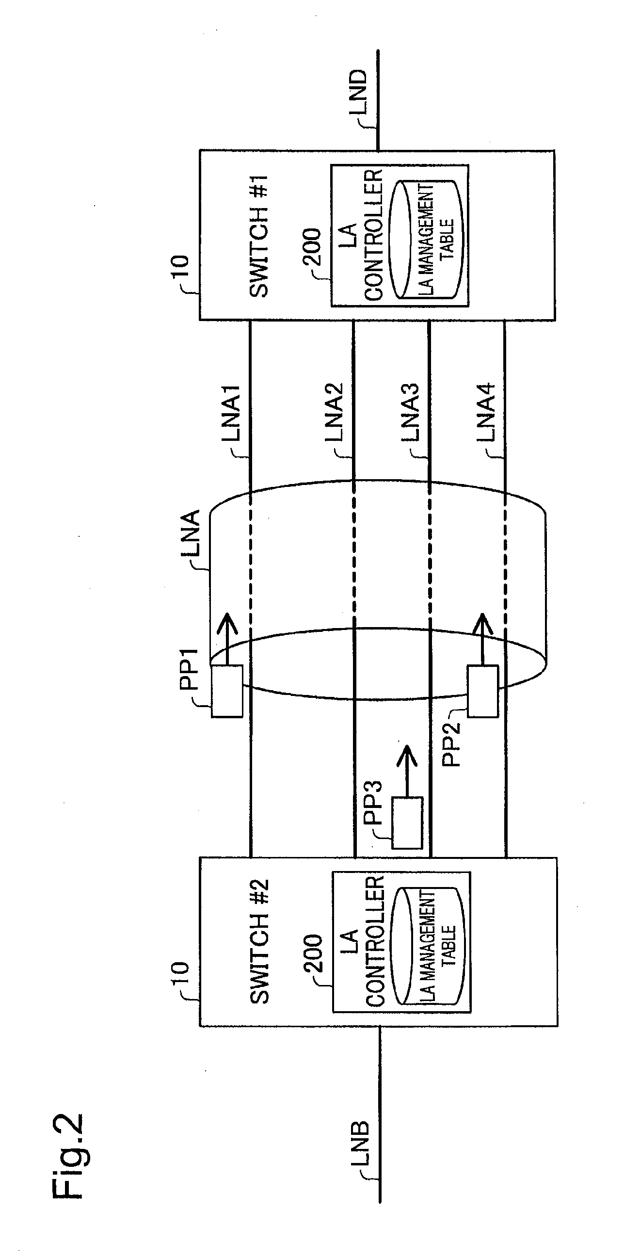
[0099]FIG. 6 is a diagram illustrating the general configuration of the switch 10 according to one embodiment of the invention. The switch 10 includes a Ring manager 100, an LA Ring mapping table 110, an LA controller 200, a frame relay module 300, frame identification modules 310 and 320, a Health check frame controller 400 and a physical line controller 500. The Ring manager 100 and the LA Ring mapping table 110 are implemented by a CPU 15 and a memory 16. The LA controller 200, the frame relay module 300, the frame identification modules 310 and 320 and the Health check frame controller 400 are implemented by an ASIC (Application Specific Integrated Circuit) 17. The physical line controller 500 is constructed by a PHY chip.

[0100]The Ring manager 100 generates, sends and receives Health check frames according to the Ring protocol, in order to monitor the status of the network and change the communication path based on a change in ...

second embodiment

C. Second Embodiment

[0201]Another configuration that employs different rules (first rule and second rule) to avoid using the same port as both the frame-sending port to send a Health check frame and the frame-receiving port to receive a Health check frame is described below as a second embodiment according to the invention. In the description and the illustrations of the second embodiment, the like constituents to those of the first embodiment are expressed by the like numerals to those of the first embodiment and are not specifically explained here.

[0202](C-1) System Configuration

[0203]FIG. 19 is a diagram illustrating the general configuration of a switch 10a according to the second embodiment. The difference from the first embodiment shown in FIG. 6 is only a Health check transmission controller 430a used in place of the Health check transmission controller 430. Otherwise the configuration and operations of the second embodiment are similar to those of the first embodiment. When ...

third embodiment

D. Third Embodiment

[0255]Another configuration that, in principle, prevents the state where the same port is used as both the frame-sending port to send a Health check frame and the frame-receiving port to receive a Health check frame, is described below as a third embodiment according to the invention. In the description and the illustrations of the third embodiment, the like constituents to those of the first embodiment are expressed by the like numerals to those of the first embodiment and are not specifically explained here.

[0256](D-1) System Configuration

[0257]FIG. 27 is a diagram illustrating the general configuration of a switch 10b according to the third embodiment. The difference from the first embodiment shown in FIG. 6 is only a Health check frame controller 400b used in place of the Health check frame controller 400. Otherwise the configuration and operations of the third embodiment are similar to those of the first embodiment.

[0258]The Health check frame controller 400b...


PUM


Abstract

The network relay device is provided. The network relay device includes: a plurality of ports, each being configured to be connectable with one physical line; a virtual line controller configured to treat a plurality of physical lines, which are respectively connected with the plurality of ports, to constitute a virtual line; and a status check frame controller configured to send via the virtual line a status check frame for use in checking status of a network, which the network relay device is connected with via the virtual line, wherein the status check frame controller changes a frame-sending port to be used to send a next status check frame, in order to avoid continuously using an identical port as both a frame-sending port to send the status check frame and a frame-receiving port to receive the status check frame from another network relay device.

Description

CROSS-REFERENCE TO RELATED APPLICATIONS[0001]The present application claims priority to Japanese Patent Application No. 2011-153690 filed on Jul. 12, 2011, the disclosure of which is hereby incorporated by reference in its entirety.BACKGROUND OF THE INVENTION[0002]1. Field of the Invention[0003]The present invention relates to a network relay device, and more specifically to detecting a failure occurring in a network, which a network relay device is connected with.[0004]2. Description of the Related Art[0005]In the Ethernet (registered trademark)-based layer 2 network, Spanning Tree protocol (STP) according to the IEEE 802.1d standard has been known as the protocol to make the switches redundant. The STP causes control frames called BPDU (Bridge Protocol Data Unit) to be exchanged between the switches, so as to logically eliminate the loop structure of routing and check the status of a network, which the switches are connected to, such as the occurrence or non-occurrence of a failur...

Claims


Application Information

Patent Timeline
Patent Type & Authority Applications(United States)
IPC IPC(8): H04L12/26
CPCH04L43/0811H04L41/06H04L12/42H04L43/0817H04L41/40
Inventor NISHIKAWA, KOICHI
Owner ALAXALA NETWORKS
Why Eureka
Try Eureka