Agricultural ram press

a technology of ram press and ram body, which is applied in the direction of packaging/bundling articles, baling, and bundling articles, can solve the problems of difficult to meet these requirements in a satisfactory manner using the conventional drive mechanism, and achieve the effect of reducing friction and wear

Active Publication Date: 2014-08-26
USINES CLAAS FRANCE
View PDF8 Cites 5 Cited by
  • Summary
  • Abstract
  • Description
  • Claims
  • Application Information

AI Technical Summary

Benefits of technology

[0010]To minimize friction and wear, the control rod preferably carries a roller that impinges upon the cam track.

Problems solved by technology

It is difficult to fulfill these requirements in a satisfactory manner using the conventional drive mechanism.

Method used


Image

  • Agricultural ram press
  • Agricultural ram press
  • Agricultural ram press

Examples


Embodiment Construction

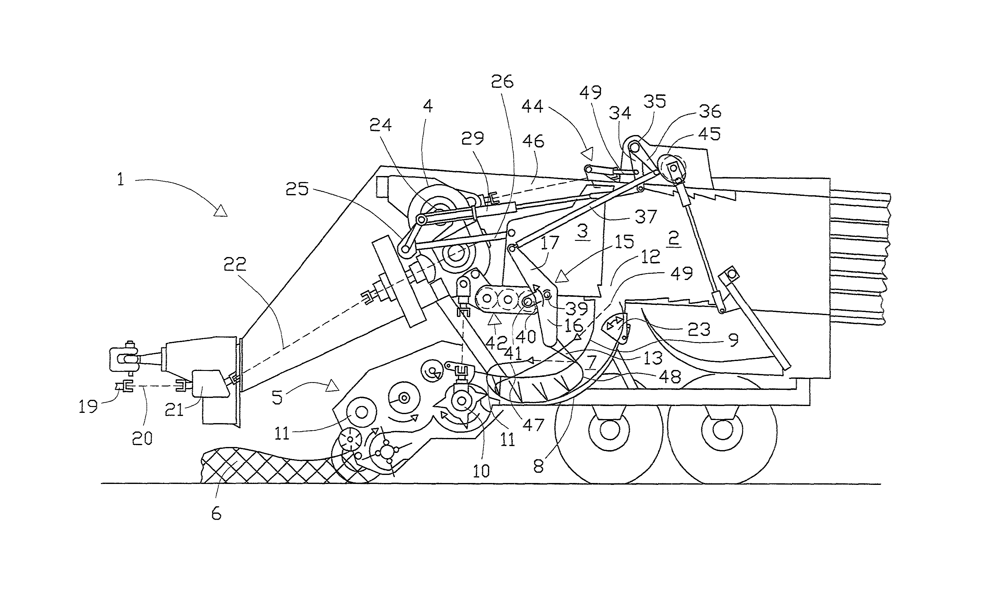
[0021]Ram press 1 shown in a schematic side view in FIG. 1 is designed as a trailer to be coupled to a towing vehicle which is not depicted. It comprises a pick-up device 5, which is also referred to as a pick-up, for picking up crop 6 from the ground.

[0022]The crop, which has been gathered by pick-up device 5 and fragmentized by a cutting device 10, is conveyed to an entrance 11 of a feed channel 7, the exit 16 of which leads into a bale chamber 2. A baling ram 3, which can move back and forth in bale chamber 2, compresses the supplied crop, wherein compressed crop located further downstream in bale chamber 2, and finished bales serve as an abutment for the compression.

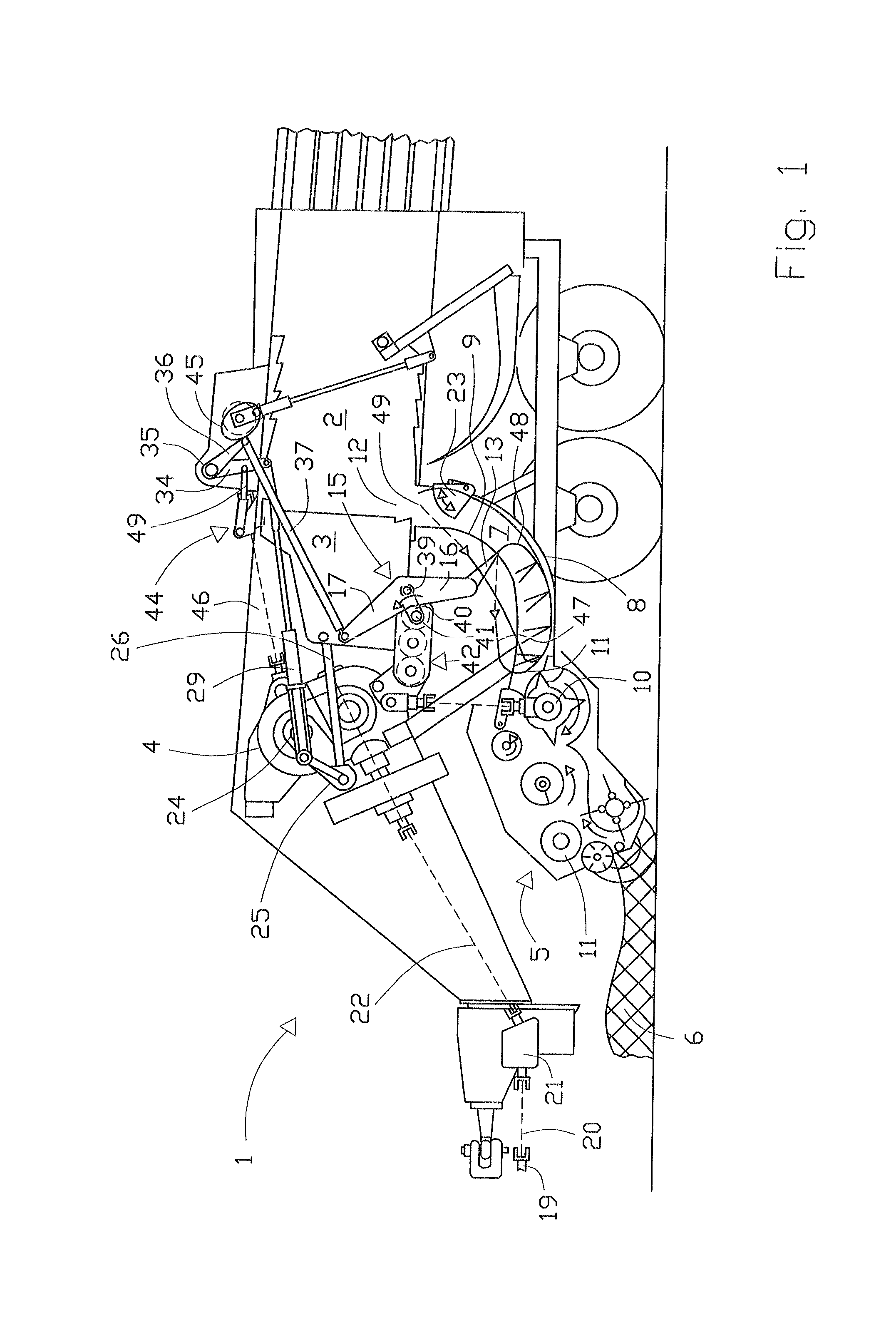
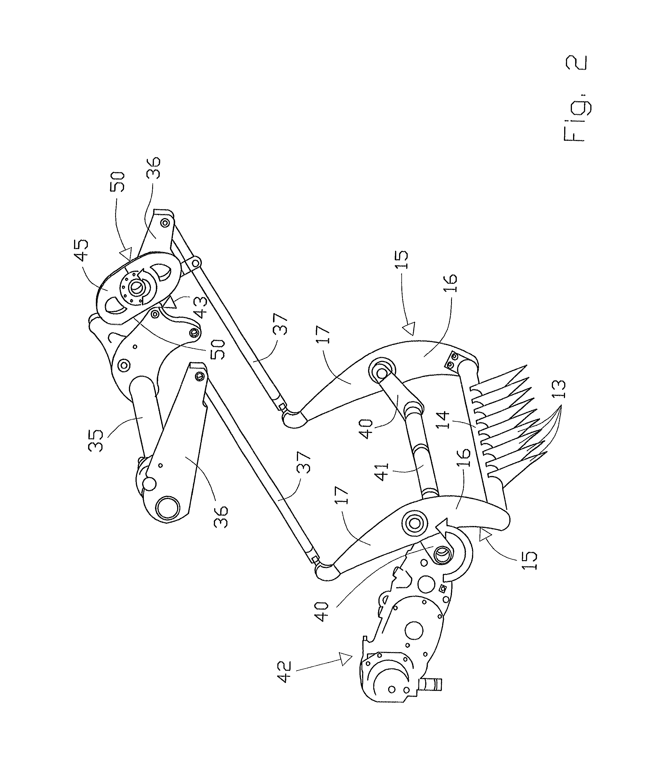
[0023]Feed channel 7 extends in the shape of a curve between entrance 11 thereof and exit 16, and is bounded by a concave base 8 and a cover 9. Cover 9 comprises a plurality of longitudinal slots through which agitator tines can enter feed channel 7. As shown in FIG. 2, agitator tines 13 are mounted on a crossmember ...


PUM


Abstract

An agricultural ram press has a bale chamber, a baling ram moveable in an oscillating manner in the bale chamber, a feed channel, a feed rake arranged in the feed channel and switchable between a gathering stroke motion which compresses crop in the feed channel and a filling stroke motion which moves the crop from the feed channel into the bale channel, and a drive for driving the feed rake and having a control rod interacting with an adjustable stop to control at least one of the motions of the feed rake.

Description

CROSS-REFERENCE TO RELATED APPLICATION[0001]The invention described and claimed hereinbelow is also described in German Patent Application DE 10 2010 037 722.8 filed on Sep. 23, 2010. This German Patent Application, whose subject matter is incorporated here by reference, provides the basis for a claim of priority of invention under 35 U.S.C. 119(a)-(d).BACKGROUND OF THE INVENTION[0002]The present invention relates to an agricultural ram press with which crop picked up from a cultivated field is pressed into bale form. Such a ram press is known from EP 1 769 674 B1, for example.[0003]This conventional ram press comprises a bale chamber in which a ram is driven in an oscillating manner in order to compress the crop conveyed into the bale chamber into a bale. The crop reaches the bale chamber via a pick-up device which gathers the crop from the cultivated field, and a feed channel in which a feed rake moves. The feed rake performs two motions, specifically a gathering stroke, in which ...

Claims


Application Information

Patent Timeline
Patent Type & Authority Patents(United States)
IPC IPC(8): B30B15/30A01F15/10
CPCA01F15/101A01F2015/102
Inventor ARNOULD, CYRILLEHESSELMANN, ULRICHALTMEYER, MARC
Owner USINES CLAAS FRANCE
Why Eureka
Try Eureka