Ipm motor and vacuum inhaling apparatus using the same

a vacuum inhalation and motor technology, applied in the direction of positive displacement liquid engines, liquid fuel engines, pumping pumps, etc., can solve the problems of difficult to employ a slim type structure, complicated internal structure of the cleaner, and inability to design the drive motor, etc., to achieve the effect of improving the inhalation efficiency, and reducing the friction resistan

Inactive Publication Date: 2010-08-05
AMOTECH
View PDF7 Cites 26 Cited by
  • Summary
  • Abstract
  • Description
  • Claims
  • Application Information

AI Technical Summary

Benefits of technology

[0042]As described above, a vacuum inhaling apparatus according to the present invention is configured to have a curved path of the shortest distance via which external air passes in which the external air passes through a circular inlet of a cover, an impeller, an air guide, a stator of a motor, and an outlet of a PCB cover, in turn, to thus make the vacuum inhaling apparatus established to have a natural airflow channel, and to thereby minimize a frictional resistance.
[0043]In addition, introduced air having passed through an upper housing moves to the inside of a motor, to thus air-cool circuit elements such as power drive devices which are mounted on a stator and a control PCB, and an air exhaustion path is established into an outlet of the PCB cover. Accordingly, the vacuum inhaling apparatus can be cooled without having a separate heat radiator.
[0044]Moreover, a rotational force of a rotor is effectively transferred to an impeller in the vacuum inhaling apparatus according to the present invention, and thus air passes through an airflow path having a short air passage route and a small amount of frictional resistance. Accordingly, a high speed airflow cools the inside of the motor, to thus greatly increase an inhalation efficiency in comparison with the conventional art and decrease electric power consumption. As a result, since an amount of heat generated from a power drive device is reduce

Problems solved by technology

Therefore, since a conventional vacuum inhalation apparatus performs a heat radiation operation with a structure that an electric power drive element of the BLDC motor is attached to a radiating fin or a radiating housing, it is difficult to employ a slim type structure that the BLDC motor is closely attached to an air guide of the vacuum inhalation apparatus.
That is, it was not possible to design the drive motor into an internal type that makes a drive motor located in a space between the air guide and a control PCB.
Accordingly, the internal structure of the cleaner becomes complicated.
Further, size of the vacuum inhalation apparatus becomes large due to the space in which the heat radiating structure is mounted.
In addition, in the case that the housing of the BLDC motor is formed of the heat radiating structure, weight of the vacuum inhalation apparatus becomes increas

Method used


Image

  • Ipm motor and vacuum inhaling apparatus using the same
  • Ipm motor and vacuum inhaling apparatus using the same
  • Ipm motor and vacuum inhaling apparatus using the same

Examples


Embodiment Construction

[0114]As described above, the present invention has been described with respect to particularly preferred embodiments. However, the present invention is not limited to the above embodiments, and it is possible for one who has an ordinary skill in the art to make various modifications and variations, without departing off the spirit of the present invention. Thus, the protective scope of the present invention is not defined within the detailed description thereof but is defined by the claims to be described later and the technical spirit of the present invention.

INDUSTRIAL APPLICABILITY

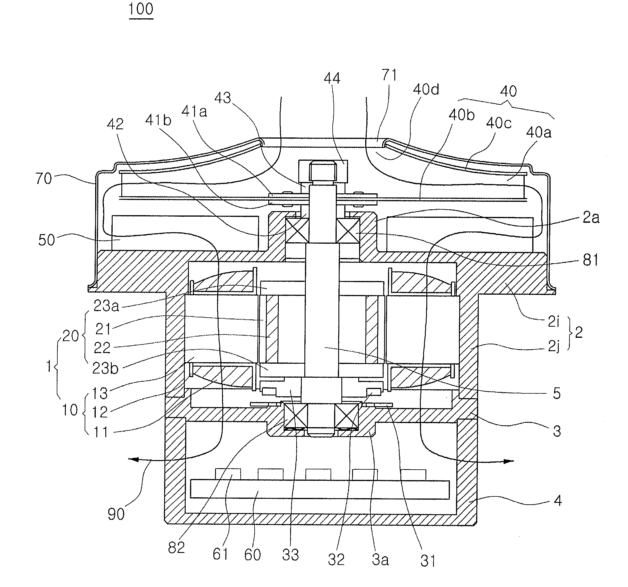
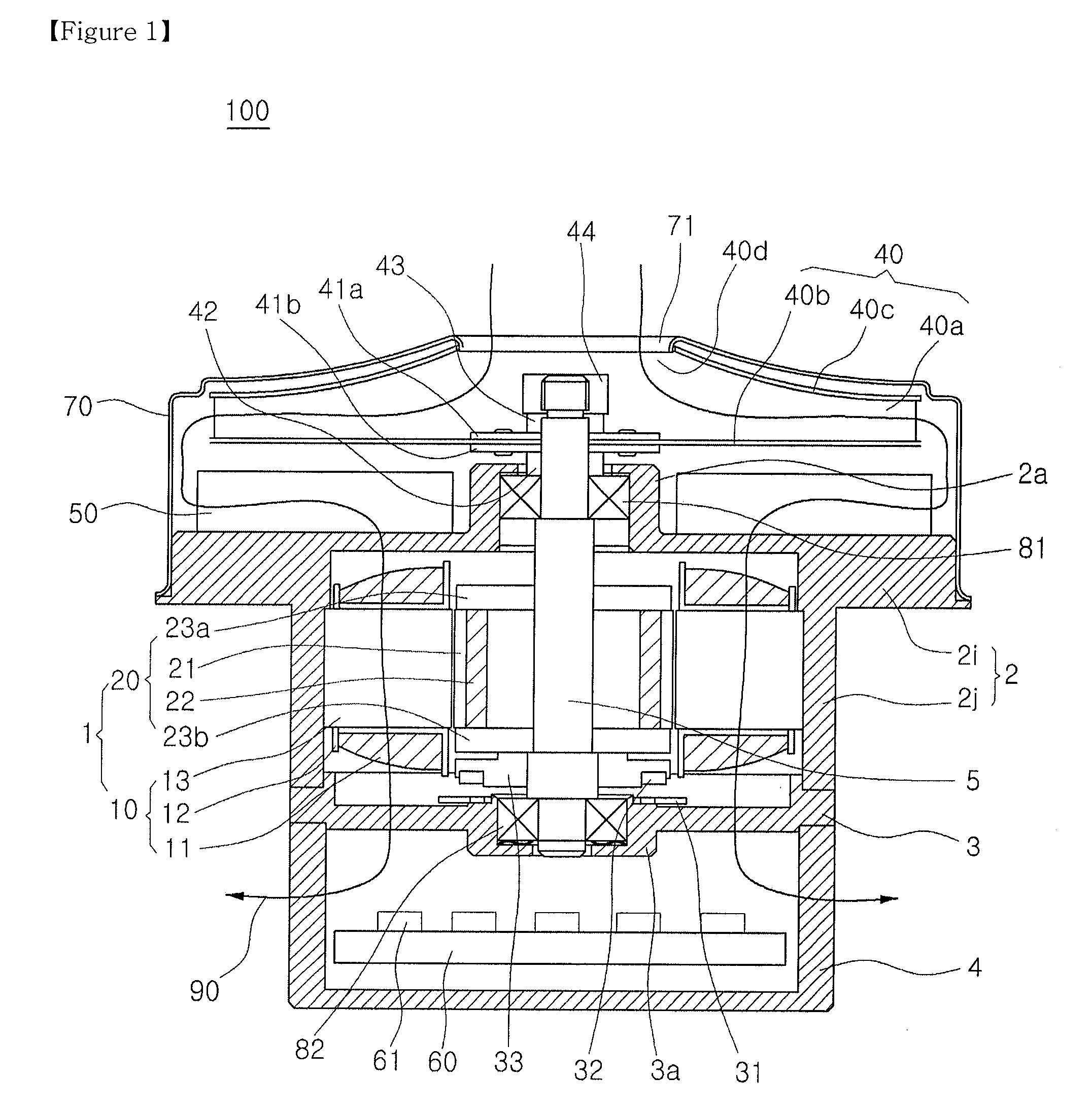
[0115]The present invention can implement an IPM motor into a compact structure, and realize high speed of 40,000 RPM and a large power output of 2,400 W in the form of a BLDC motor. Accordingly, the present invention can be applied to a vacuum cleaner, a battery car, etc.


PUM


Abstract

Provided is a high speed and high efficiency IPM (Interior Permanent Magnet) motor and a slim type vacuum inhaling apparatus using the same, which establishes a passage path of introduced air into a path of air-cooling the inside of a stator and a circuit element to thus cool heat that is produced from the IPM motor without a special heat radiator. The IPM motor includes: a stator having a number of tees which are protruded so as to form a number of slots on the inner circumferential wall of a cylindrical body, and a stator coil which is partially wound around the slots; and an IPM type rotor having a rotor core at the central side of which a rotating shaft is mounted, and a number of permanent magnets which are fitted into a number of permanent magnet insertion holes which are formed on the identical circumference of the rotor core, and which is rotated by the stator.

Description

TECHNICAL FIELD[0001]This invention relates to an IPM (Interior Permanent Magnet) motor and a vacuum inhalation apparatus using the same, and more particularly, to a high speed and high efficiency IPM motor and a slim type vacuum inhaling apparatus using the same, which employs the IPM motor having little heat generation by electric current in the inside of a rotor and establishes a passage path of introduced air into a path of air-cooling the inside of a stator and a circuit element to thus cool heat that is produced from the IPM motor without a special heat radiator.BACKGROUND ART[0002]Today, a number of electric home appliances are being developed and marketed. Among the number of electric home appliances, a vacuum cleaner is developed for cleanliness of a residence environment.[0003]Vacuum cleaners are electric appliances which inhale air including foreign matters such as dust using a vacuum pressure generated by an impeller and a BLDG (brushless DC) motor that are installed in ...

Claims


Application Information

Patent Timeline
IPC IPC(8): F04D25/06H02K21/14
CPCF04D25/082F04D25/0606F04D29/5806F04D25/06H02K7/00F04B9/00
Inventor LEE, JONG HOON
Owner AMOTECH
Why Eureka
Try Eureka