Temperature adaptive dynamic shaft seal assembly

a dynamic shaft and seal technology, applied in the direction of engine seals, mechanical equipment, engine components, etc., can solve the problems of accelerating wear, leakage rate, shortening the service life of the seal assembly, etc., to achieve excellent adjustable sealing, minimize unnecessary friction and wear, and minimize friction

Active Publication Date: 2013-08-13
GM GLOBAL TECH OPERATIONS LLC
View PDF27 Cites 6 Cited by
  • Summary
  • Abstract
  • Description
  • Claims
  • Application Information

AI Technical Summary

Benefits of technology

[0008]The seal assemblies of the present invention provide excellent adjustable sealing against dynamic shafts, e.g., rotating, reciprocating, and / or oscillating shafts. In particular, the seal assemblies provide adjustable compression force and on-demand sealing across a range of operating pressures and temperatures to minimize unnecessary friction and wear between the elastic seal member and the dynamic shaft. Therefore, the seal assemblies exhibit minimal friction and leaking between the elastic seal member and the dynamic shaft, and excellent elastic seal member service life, durability, and reliability. Additionally, the shape memory alloy elements of desired length apply uniform pressure along an entire length of the shape memory alloy element, and therefore, minimize undesired rubbing between the coil spring and the shape memory alloy element. The crimp further minimizes such undesired rubbing. The seal assemblies are also cost-effective and suitable for operating conditions requiring elevated pressures.

Problems solved by technology

However, leakage rates and maximum friction tolerances are often competing requirements.
However, increased compression force also often increases friction between the elastic seal member and the dynamic shaft, accelerates wear, and shortens a service life of the seal assembly.
Conversely, reduced compression force often results in a poor seal and an undesirable leakage rate.

Method used


Image

  • Temperature adaptive dynamic shaft seal assembly
  • Temperature adaptive dynamic shaft seal assembly
  • Temperature adaptive dynamic shaft seal assembly

Examples


Embodiment Construction

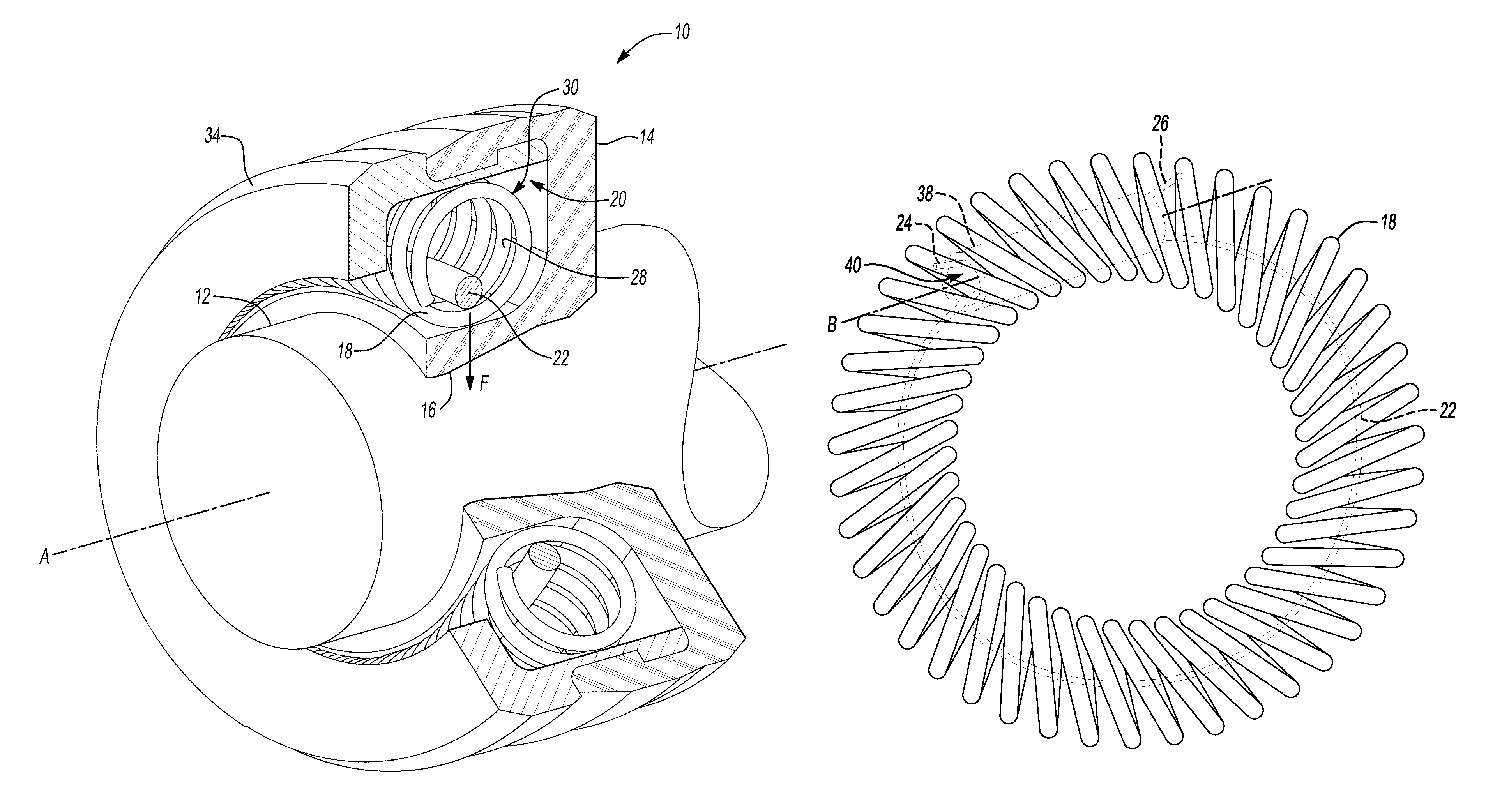
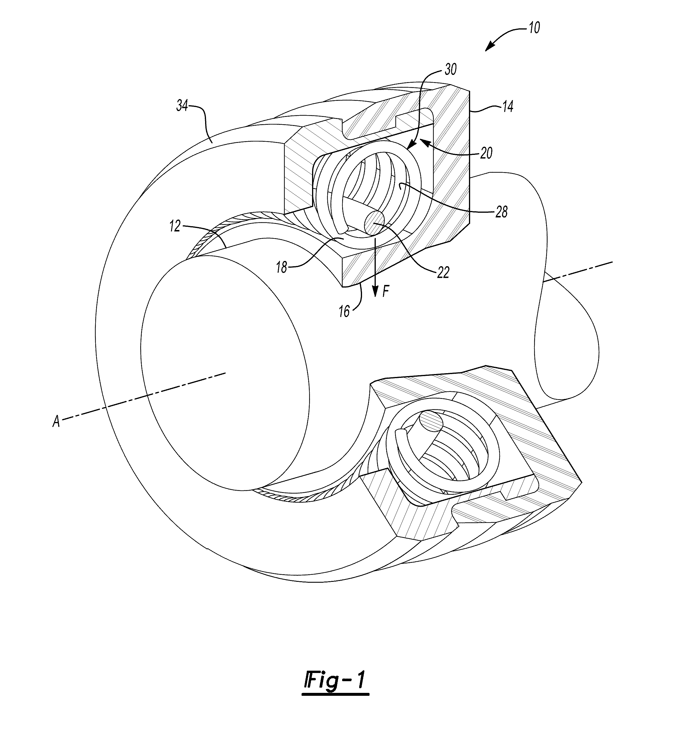
[0018]Referring to the Figures, wherein like reference numerals refer to like elements, a seal assembly is shown generally at 10 in FIG. 1. The seal assembly 10 is configured for sealing a dynamic shaft 12, e.g., a rotating, reciprocating, and / or oscillating shaft. Therefore, the seal assembly 10 may be useful for applications such as, but not limited to, automotive actuators and dampers in engine, transmission, driveline, suspension, and braking sub-systems. However, it is to be appreciated that the seal assembly 10 may also be useful for non-automotive applications such as, but not limited to, hydraulic industrial pumps, construction equipment gearbox assemblies, washing machine tubs, and high-pressure fire hoses.

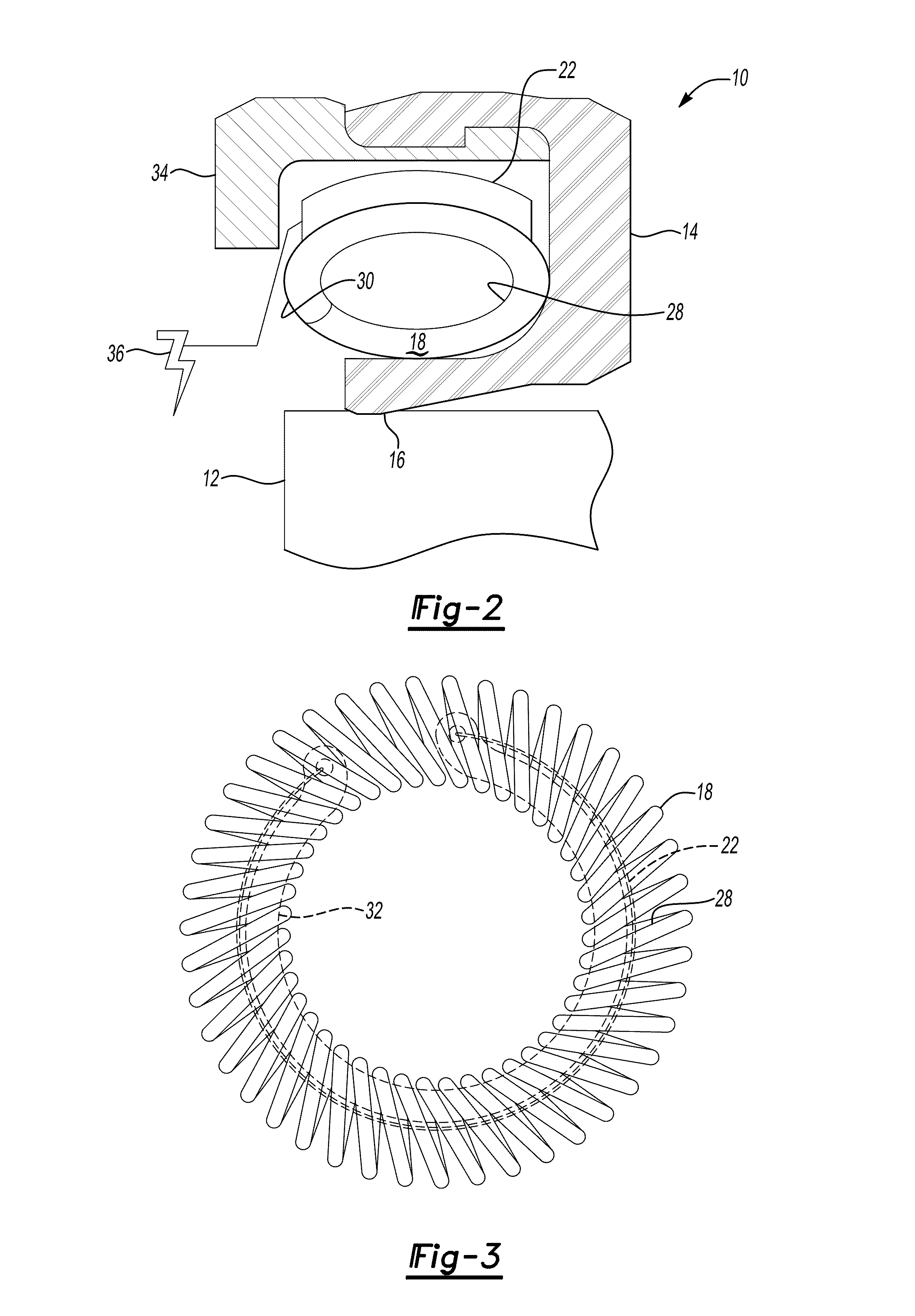
[0019]Referring to FIG. 1, the seal assembly 10 includes an elastic seal member 14 disposable in sealing communication with the dynamic shaft 12. That is, the elastic seal member 14 may have at least a portion thereof, e.g., a seal lip 16, disposed in contact with the dyn...


PUM


Abstract

A seal assembly configured for sealing a dynamic shaft includes an elastic seal member disposable in sealing communication with the dynamic shaft. The seal assembly further includes a coil spring and a shape memory alloy element. The coil spring is disposed in contact with the elastic seal member and configured for applying a compressive force to the elastic seal member. The shape memory alloy element is configured for applying pressure to the coil spring to thereby augment the compressive force.

Description

CROSS-REFERENCE TO RELATED APPLICATIONS[0001]This application is a continuation-in-part of U.S. patent application Ser. No. 11 / 536,022, filed on Sep. 28, 2006.TECHNICAL FIELD[0002]The present invention generally relates to seal assemblies, and more specifically, to seal assemblies configured for sealing dynamic shafts.BACKGROUND OF THE INVENTION[0003]Dynamic shafts, e.g., rotating, reciprocating, and / or oscillating shafts, often require seal assemblies capable of preventing ingress or egress of fluids and contaminants into and / or out of a region. Therefore, seal assemblies often include an elastic seal member capable of pressing against the dynamic shaft to form a seal. Such seal assemblies must often perform within specified leakage rates and maximum friction tolerances for a given operating temperature.[0004]However, leakage rates and maximum friction tolerances are often competing requirements. For example, increased compression force is generally required to hold the elastic sea...

Claims


Application Information

Patent Timeline
Patent Type & Authority Patents(United States)
IPC IPC(8): F16J15/32F16J15/00
CPCF16J15/164F16J15/3212F16J15/3236
Inventor GAO, XIUJIEBROWNE, ALAN L.JOHNSON, NANCY L.
Owner GM GLOBAL TECH OPERATIONS LLC
Why Eureka
Try Eureka