Method and apparatus for milling a component of a turbo-engine

Inactive Publication Date: 2007-06-07
MTU AERO ENGINES GMBH
View PDF16 Cites 7 Cited by
  • Summary
  • Abstract
  • Description
  • Claims
  • Application Information

AI Technical Summary

Benefits of technology

[0006] Within the meaning of the present invention, a milling cutter whose cutting edges are contoured with projections and recesses is used for trochoidal milling. Such contouring of the cutting edges of the milling cutter is also referred to as knurled gearing. Use of such a milling cutter has the advantage that the chips produced in milling have a mu

Problems solved by technology

Due to the geometry of this milling cutter and its motion, a very large chip volume is generated per unit of time with a relatively large chip geometry in trochoidal milling, which is

Method used


Image

  • Method and apparatus for milling a component of a turbo-engine
  • Method and apparatus for milling a component of a turbo-engine

Examples


Example

DETAILED DESCRIPTION OF THE DRAWINGS

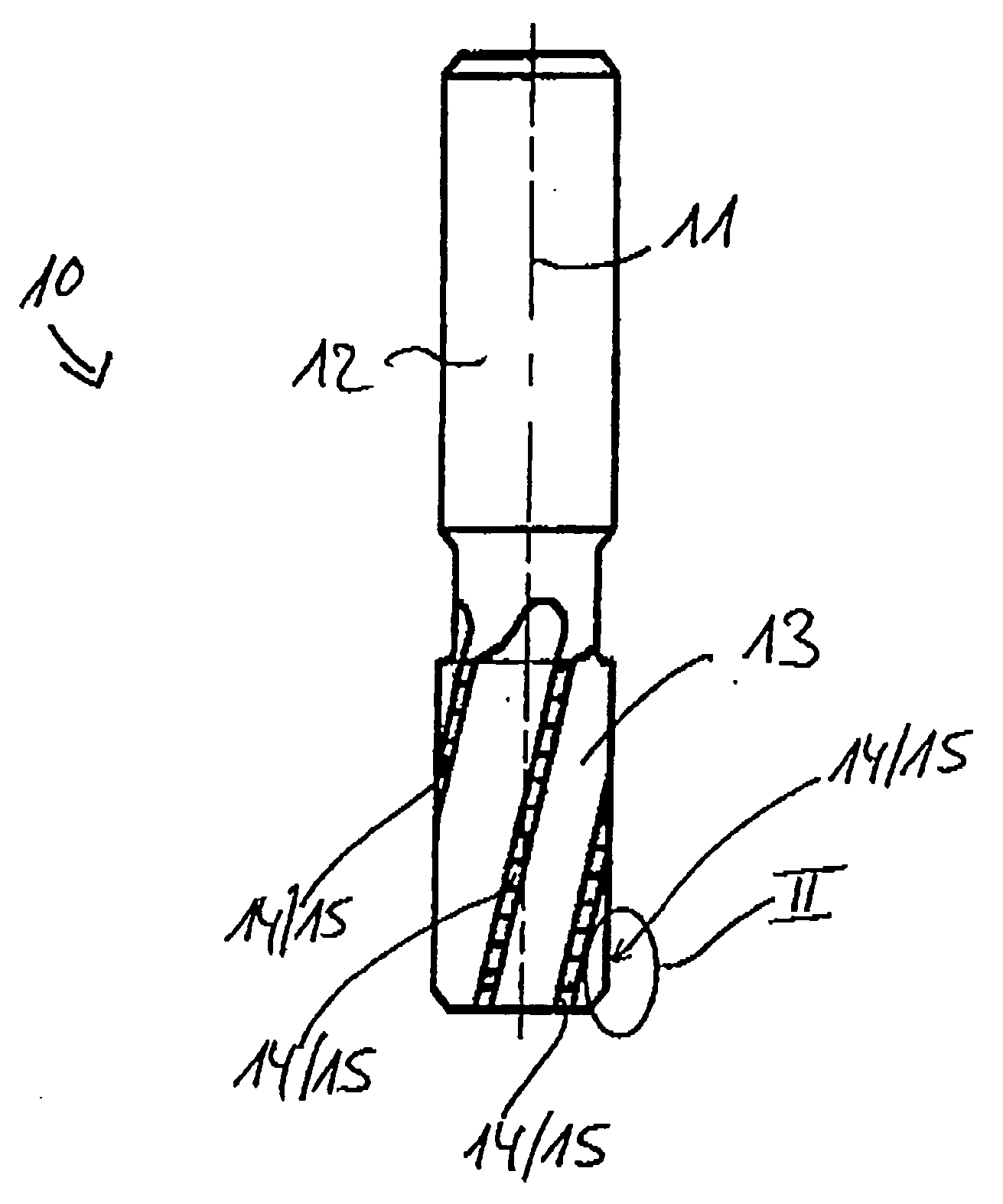
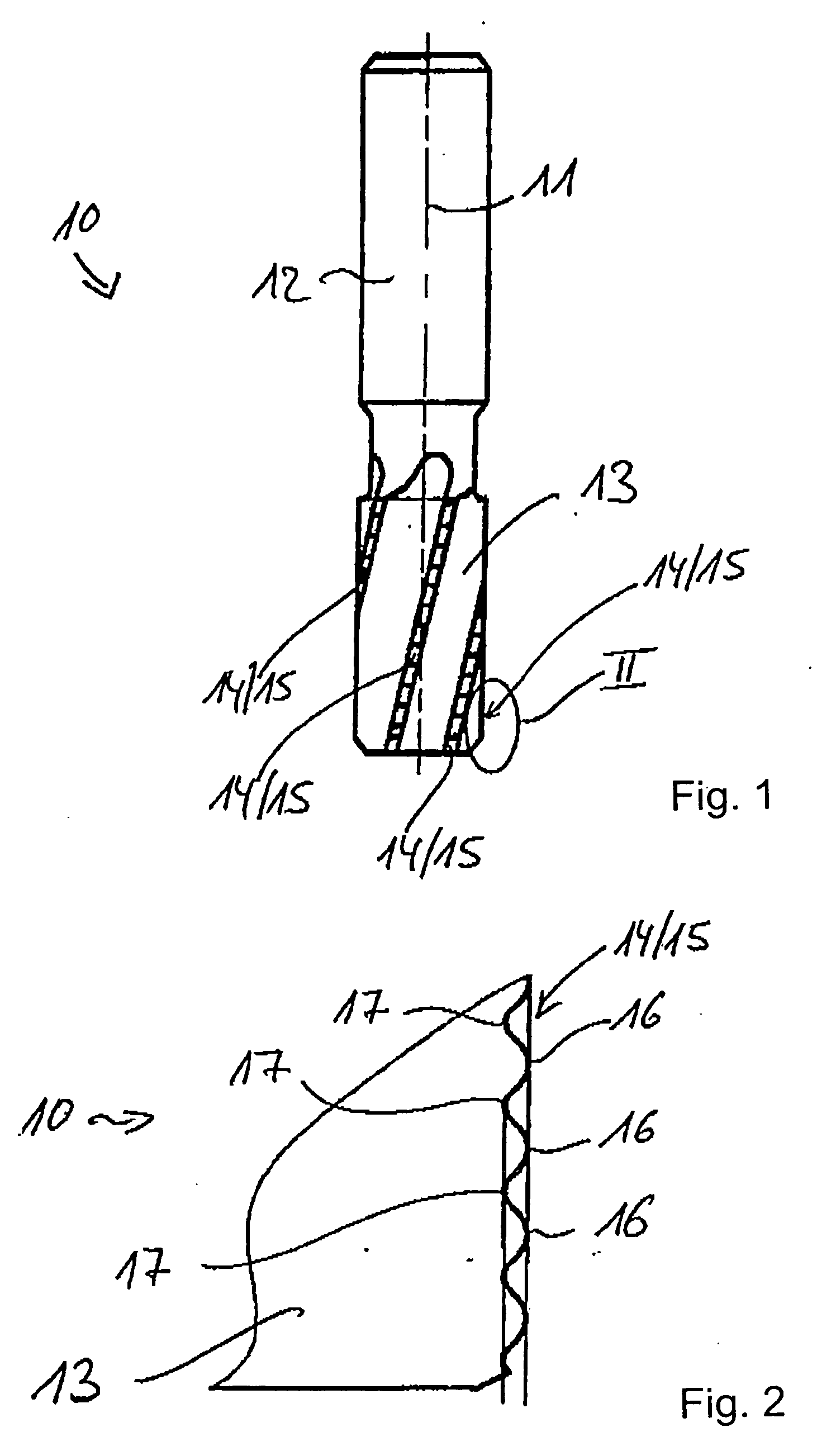
[0011] The invention relates to a milling method and apparatus for fabrication of components from difficult-to-machine materials for turbo-engines, producing recesses having one or more side walls. The inventive milling method and apparatus is used in particular for fabrication of integrally bladed rotors for gas turbines in which the recesses form flow channels and the side walls form blade surfaces of the integrally bladed rotor to be manufactured.

[0012] The inventive milling method is a trochoidal milling method; details of trochoidal milling are known from DE 102 19 012 B4, and U.S. Patent Application Publication 2003 / 0202854 A1 which is a family member of DE 102 19 012, the disclosures of which are hereby incorporated by reference herein. For the sake of thoroughness, it should be pointed out here that in trochoidal milling, a milling cutter rotates centrally around an axis of the milling cutter, whereby the milling cutter additionally exec...


PUM

PropertyMeasurementUnit
Shapeaaaaaaaaaa
Distanceaaaaaaaaaa

Abstract

A milling method and apparatus for the fabrication of components from materials that are difficult to cut for turbo-engines, producing recesses having one or more side walls, in particular for the fabrication of integrally bladed rotors for gas turbines, in which the recesses form flow channels and the side walls form blade surfaces of an integrally bladed rotor, are disclosed. A milling cutter rotates centrally about an axis of a milling machine. The milling cutter additionally executes an eccentric circular motion about a circular path axis at a distance from the axis of the milling machine. The axis of the circular path including the milling cutter executes an advance motion on a straight and/or curved path. The milling cutter includes cutting edges that are contoured with projections and recesses.

Description

[0001] This application claims the priority of European Patent Application No. 05 021 985.6, filed Oct. 8, 2005, the disclosure of which is expressly incorporated by reference herein. BACKGROUND AND SUMMARY OF THE INVENTION [0002] The invention relates to a method and apparatus for milling. [0003] German Patent Document No. DE 102 19 012 B4 discloses a milling method for the fabrication of components from difficult-to-machine materials for turbo-engines. The milling method disclosed there is used in particular for the fabrication of integrally bladed rotors for gas turbines, where recesses to be milled form flow channels, and the side walls bordering the recesses form blade surfaces of the integrally bladed gas turbine rotor. In the milling method according to DE 102 19 012 B4, a milling cutter is driven to rotate about the milling axis such that the milling cutter executes an eccentric rotary motion about a circular path axis at a distance from the axis of the milling machine in ad...

Claims


Application Information

Patent Timeline
IPC IPC(8): B23C3/00
CPCB23C3/18B23C5/10B23C2210/0485Y10T29/49325B23C2210/54Y10T409/303808Y10T29/49995B23C2210/088
Inventor HEINRICH, STEFANGLAESSER, ARNDTLEBKUECHNER, GOETZ
Owner MTU AERO ENGINES GMBH
Why Eureka
Try Eureka