Hydraulic Radial-piston Pump for Wind Turbines

a radial piston and wind turbine technology, applied in the direction of pump components, piston pumps, positive displacement liquid engines, etc., can solve the problems of high cost, reduce the efficiency of the piston assembly, and consume space, so as to reduce friction and compression losses, reduce friction and wear, and minimize friction and wear

Inactive Publication Date: 2014-03-27
VALENTIN INGO
View PDF0 Cites 6 Cited by
  • Summary
  • Abstract
  • Description
  • Claims
  • Application Information

AI Technical Summary

Benefits of technology

[0014]The nearly fully hydrostatically balanced loads and forces, and the self-alignment of all moving parts significantly reduces leakage and minimizes friction and wear. The form-locked bearing mechanisms replace the function of the piston spring, reducing the friction and compression losses.

Problems solved by technology

The mechanism contains is space consuming, and the movement of the larger number of additional parts will reduce the gains in efficiency from the piston assembly.
The high loads and large size of the roller bearings result in high costs, and the limited space in axial direction does not favor the use of hydrostatic rings.
The circular shaped cylinder end requires large space for the bearing in circumferential direct at the spherical cam lobe, reducing the number of piston assemblies arranged around the cam shaft and increasing the manufacturing costs.
The efficiencies, life expectancies, and scalability of hydraulic pumps and motor of prior art are insufficient to use hydrostatic drive systems for large powers at low speeds, like wind or water turbines.
The proportionally increasing manufacturing tolerances, misalignments, and deformation of components, significantly increase the contact forces and leakage due to tilting, leading to lower efficiencies and excessive wear and likely destruction.

Method used


Image

  • Hydraulic Radial-piston Pump for Wind Turbines
  • Hydraulic Radial-piston Pump for Wind Turbines
  • Hydraulic Radial-piston Pump for Wind Turbines

Examples


Embodiment Construction

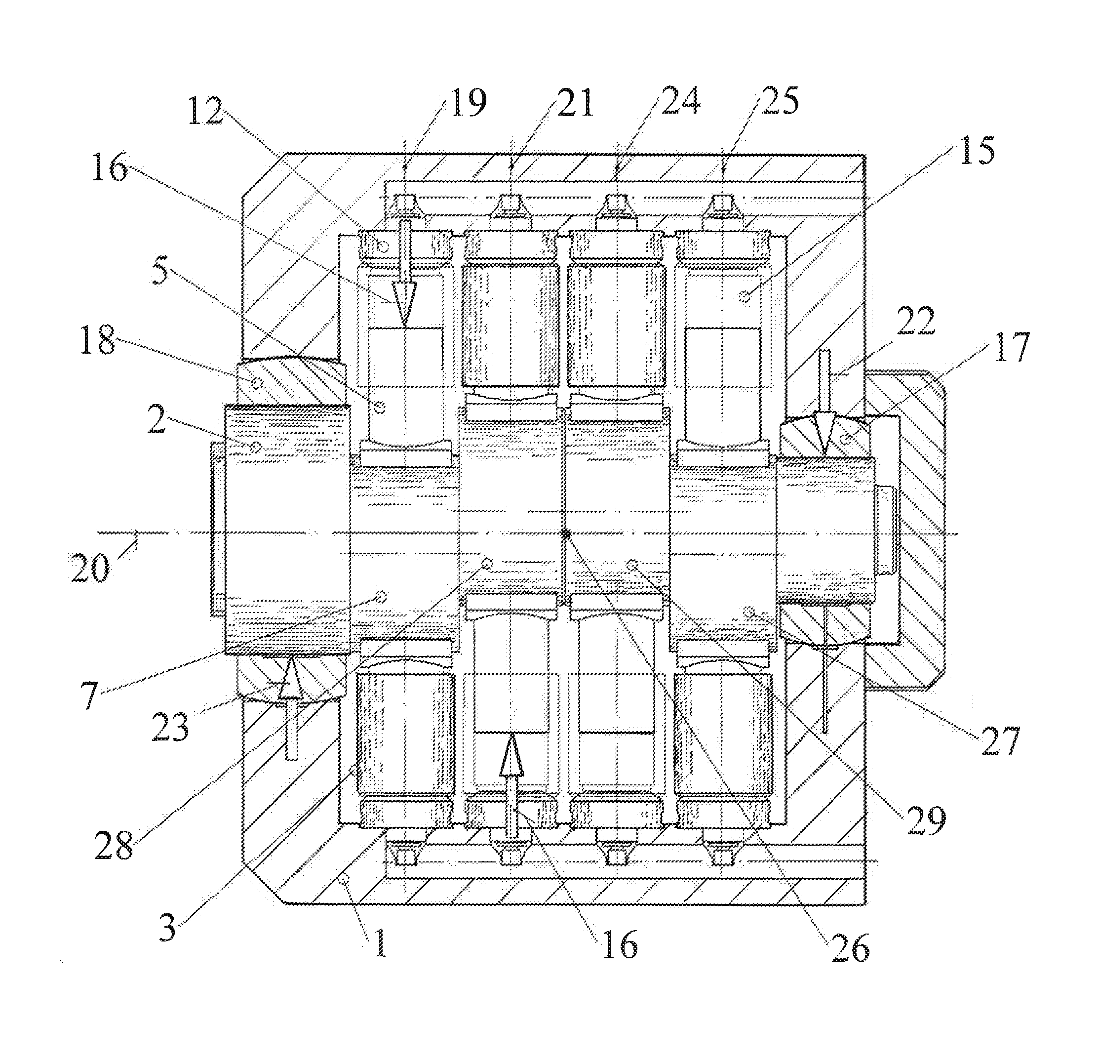
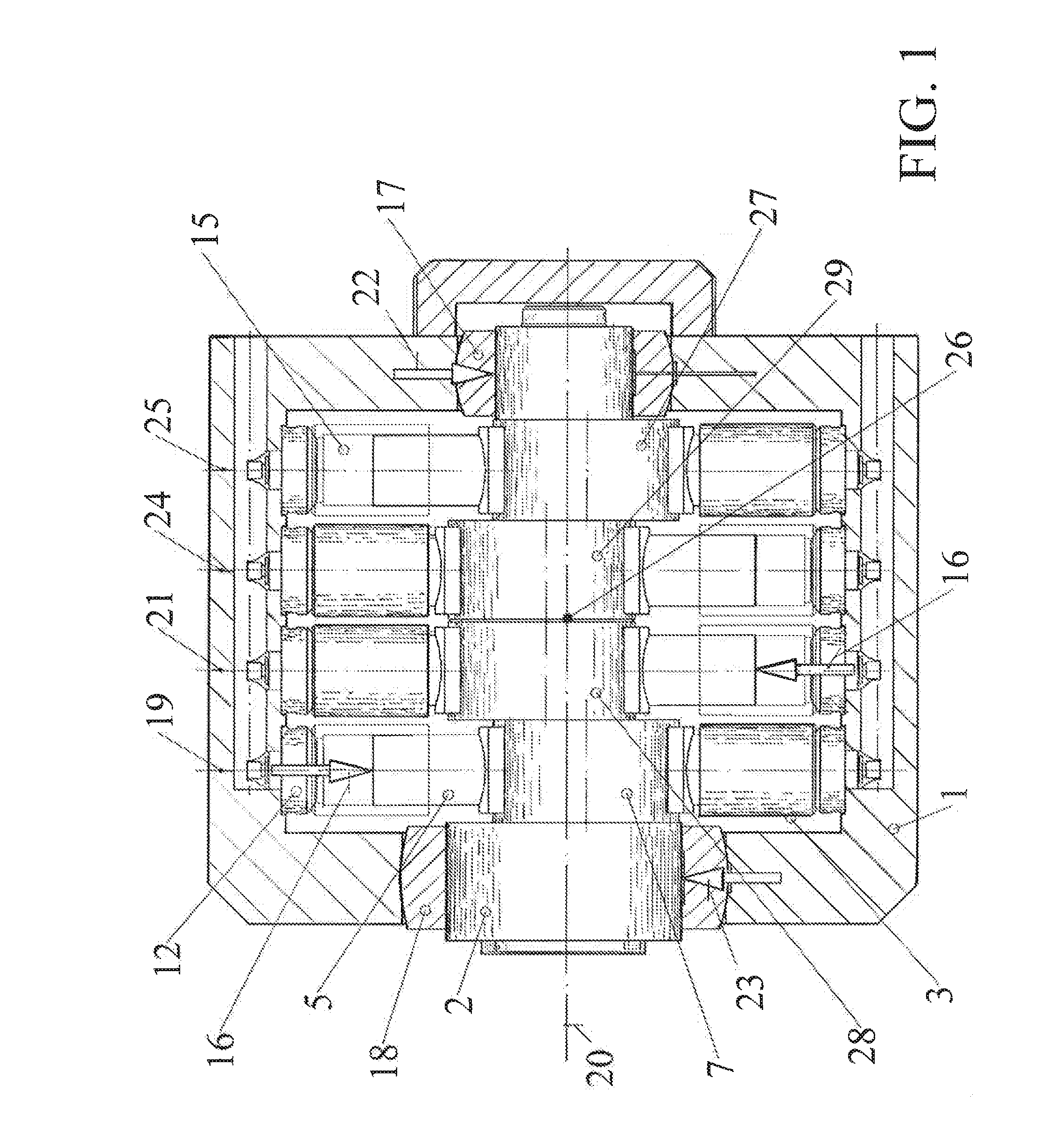
[0021]The new pump (FIG. 1) consists of housing 1, a centrally located camshaft 2 and cylinder assemblies 3 located in radial direction between camshaft and housing.

[0022]Rotation of the camshaft, results in a reciprocating movement of the piston within the cylinder, creating a pumping action.

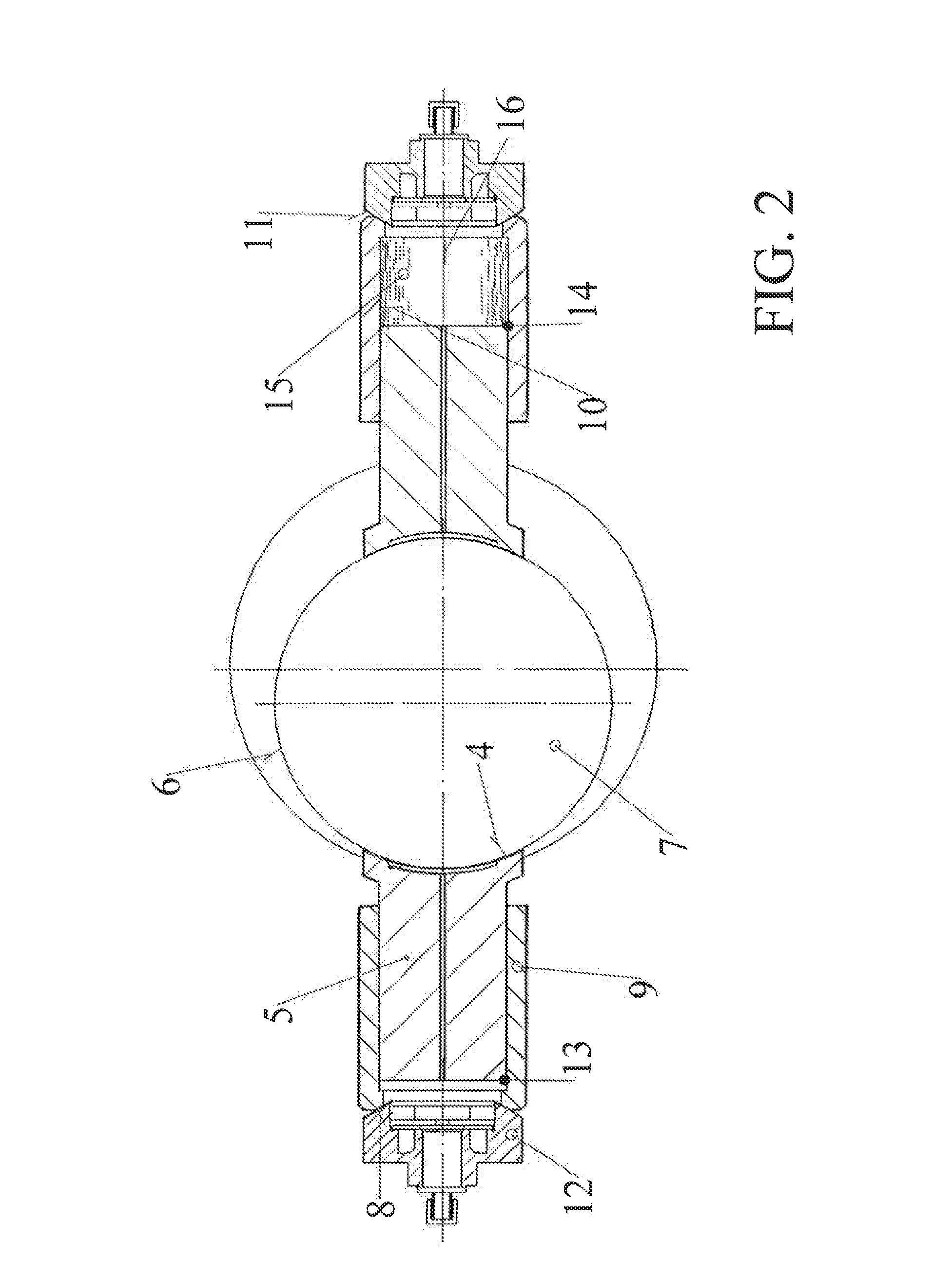
[0023]The cylindrical face 4 (FIG. 2) of piston 5 is in sliding contact with the cylindrical face 6 of cam 7 of the camshaft.

[0024]The spherical face 8 of the cylinder 9 at the opposite end of the cylinder bore 10 is in sliding contact with the spherical face 11 of cylinder joint 12.

[0025]The pivotal movement of cylinder 9 allows for a self-adjustment of cylindrical face 4 of the piston to the cylindrical face 6 of the cam shaft, significantly reducing leakage, friction, and wear.

Piston Force Compensation

[0026]The cam 7(FIG. 2) advances the piston from Bottom End Position (BEP) 13 to Top End Position (TEP) 14, and piston chamber 15 receives fluid through cylinder joint 12 during the first half ...


PUM


Abstract

A hydraulic radial-piston pump transfers the wind energy of the rotor to an adjustable hydraulic motor on ground level, driving an electric generator with constant speed. The pump consists of piston assemblies, located in radial direction between camshaft and housing, supported by spherical bearings at the housing and cylindrical bearings at the camshaft, allowing for self-adjustment of the assemblies. The radial and axial bearings of the camshaft are pivotally mounted allowing for self-adjustment to the housing. At least two planes with cams opposing each other compensate the piston forces in radial direction. Preferably, the pump has four planes symmetrically arranged around a plane between the second and third plane, compensating the piston forces in axial direction. The center of gravity of the rotor is located between or near the bearings of the camshaft. The loads are supported by hydraulic pressure fields, minimizing frictional losses and increasing longevity.

Description

BACKGROUND OF THE INVENTION[0001]1. Technical Field[0002]The invention relates to a hydrostatic transmission, transferring the power from the rotor of a wind turbine or other high torque-low speed applications like water turbines, to the electric generator through pressurized fluid. The transmission consists of a hydraulic radial-piston pump integrated into the rotor hub and axial-piston motor with variable displacement driving the generator with constant speed.[0003]Currently, geared transmissions are utilized to increase the low rotational speed of the rotor to the high speed needed at the generator. The inconsistent speed of the generator requires a complex circuitry and the gear boxes have a short operational life span and cause extensive costs for maintenance and overhaul. The high weight of the rotor, nacelle, gear box and generator on top of the tower requires a heavy tower and foundation. New drivetrain systems are utilized where the rotor drives a low speed generator direct...

Claims


Application Information

Patent Timeline
Patent Type & Authority Applications(United States)
IPC IPC(8): F04B9/04
CPCF04B9/042
Inventor VALENTIN, INGO
Owner VALENTIN INGO
Why Eureka
Try Eureka