[0014]Thus, according to the invention, it has been realized that either by combining measured values of at least the speed of the vehicle engine and a magnitude which is related to the torque of the output shaft or by eliminating the centrifugal clutch of the primary variator and, instead, provide an electronically controlled actuator operating on the variator, it is possible to provide a considerably more controllable transmission which besides has considerably better relation to the operating conditions. For example, the friction against the ground, i.e. the grip, may suddenly practically disappear and then immediately become very high. Under such conditions the V-belt CVT can be set more accurately by a control device according to the invention than by using prior-art technique.
[0016]In one embodiment of the control device according to the invention, the second measured value represents the torque of the output drive shaft. The advantage of this measured value is that it gives direct information about the operating conditions prevailing on the output side of the CVT and enables a quickly acting control device.
[0017]In one embodiment of the control device according to the invention, the control unit is adapted to control the CVT so that a predetermined relationship between the measured values is achieved in each operating situation. This gives the advantage of a simple calculation which the control unit is to perform. It also facilitates the work for a person skilled in the art who is to design the character of the drive. Different templates or schedules for the operation, which give different characters, can easily be created by combining the measured values in different ways. This is used in one embodiment of the control device to allow it to be set in different operating modes which give different relationships between the measured values in a specific operating situation. This embodiment can advantageously be used as follows. A driver of a vehicle with an engine whose V-belt CVT is controlled by a control device according to the invention can be given an opportunity to set different operating modes by himself. Depending on the ground conditions, the driver's personality etc, an individual and situation-adapted setting of the character of the V-belt CVT can thus be provided. In contrast to the construction shown in EP 701 073, the change in the gear ratio of the CVT in response to a change of the operating conditions, such as friction against the ground, can thus be set. For instance, an increase or decrease of the gear ratio, i.e. shifting, may occur according to a steeper or flatter curve. Moreover, for instance said increase / decrease can occur at different degrees of steepness in different parts of a total operating range. This will be described and exemplified in more detail below.
[0019]In one embodiment of the control device, the control unit is adapted to command the clamping power actuator to cause engagement of the primary variator at a settable first engine speed and to set the actuator to maximum clamping power at a settable second engine speed. At least according to this embodiment, it is possible to simplify a primary variator of the above-described frequently used prior-art construction, implying that the centrifugal clutch can be excluded. Instead it will be the control unit that fully determines the position of the movable pulley half in relation to the fixed pulley half. The actuator actively performs the setting at all speeds in contrast to the engagement performed by the centrifugal clutch, which is disclosed in EP 701 073 and which is not settable for different speeds unless a mechanical modification of the primary variator is made. Thus, this embodiment results in more freedom in the designing of the character of the V-belt CVT. Both the first speed, i.e. the engagement speed, and the second speed, i.e. the maximum speed, are settable.
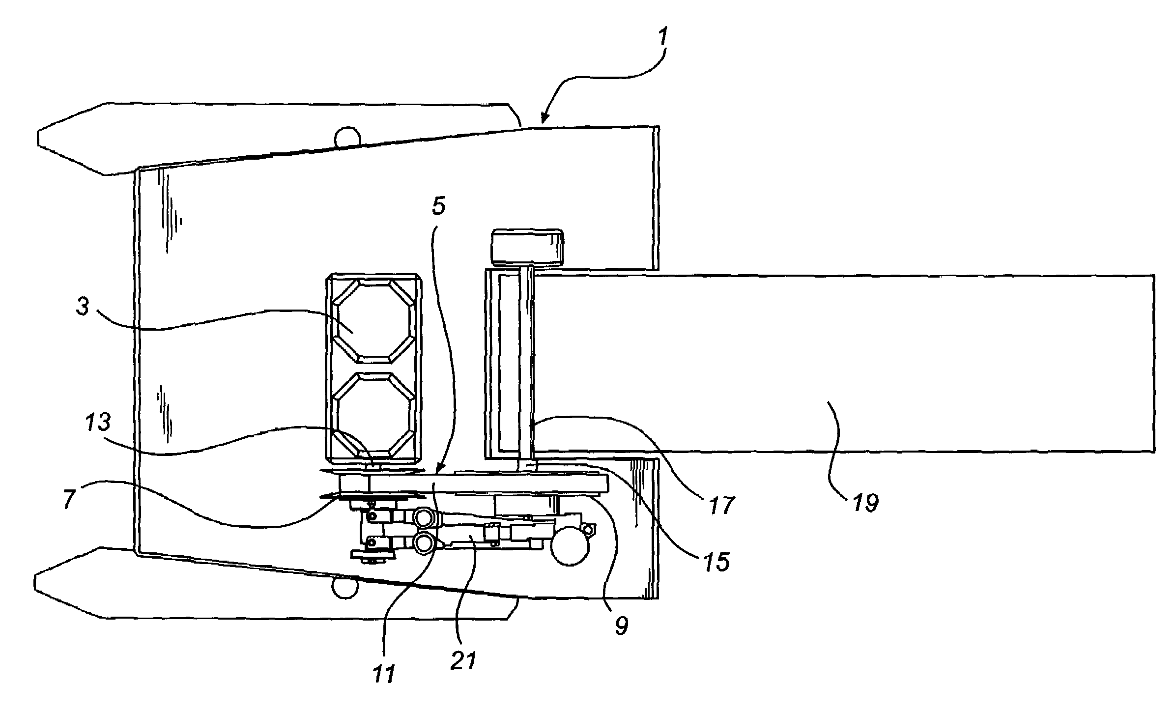
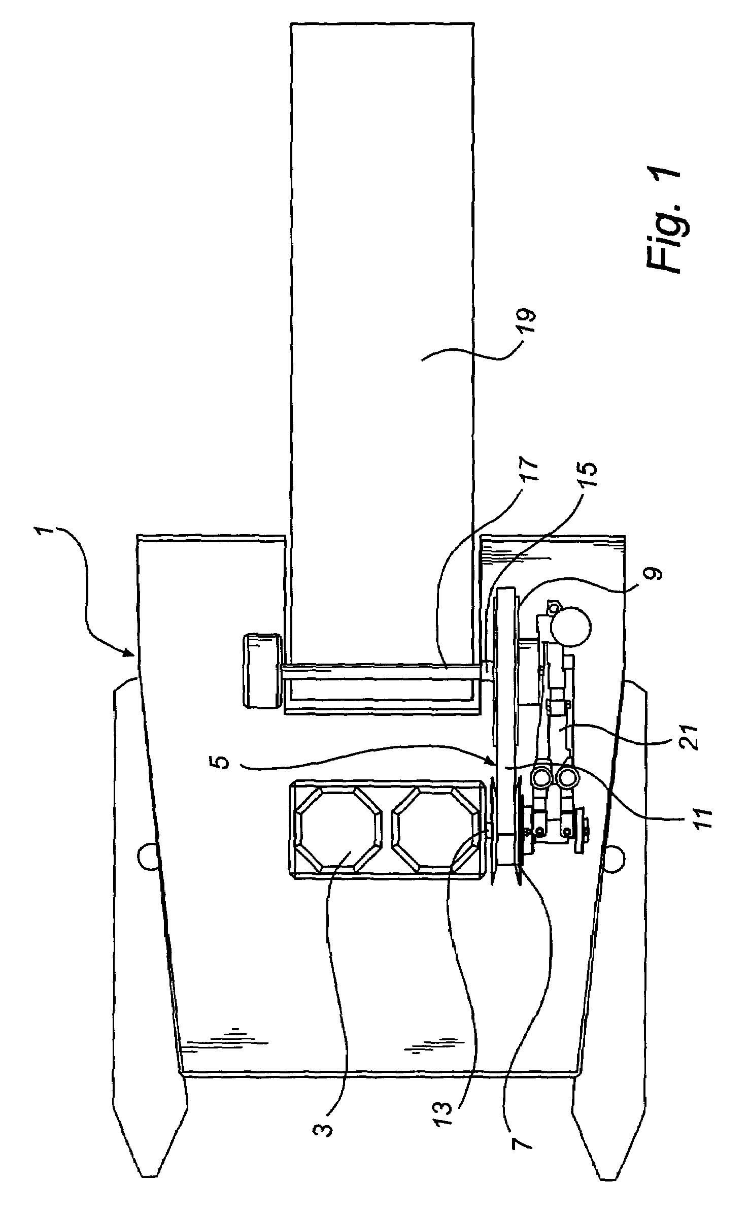
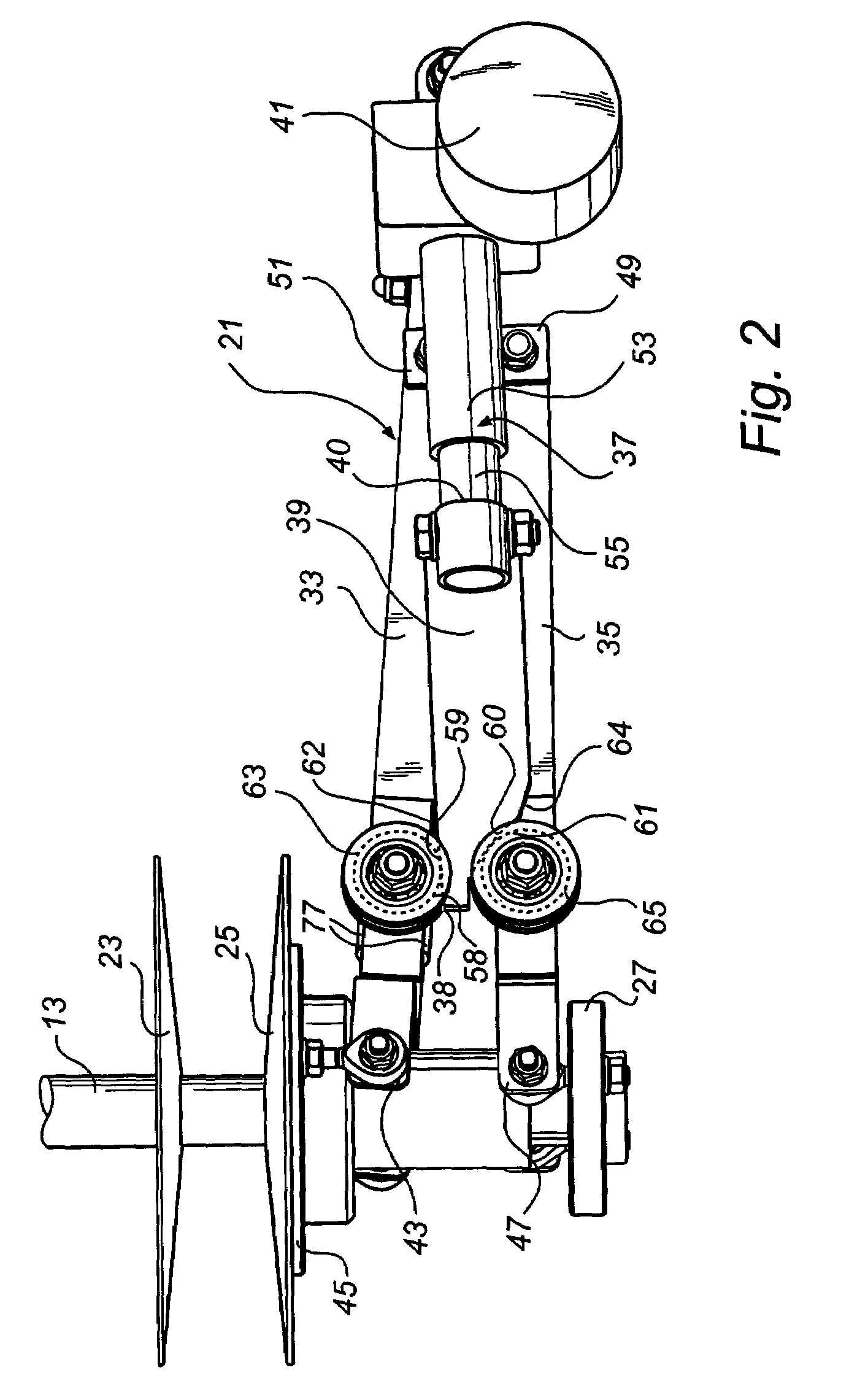
[0020]In one embodiment of the V-belt CVT, the primary variator comprises, like the above-described prior-art primary variators, a fixed pulley half which is fixedly connectible to the crankshaft of the engine, and a movable pulley shaft which is displaceably connectible to the crankshaft. Moreover the actuator comprises a holding-up means, which is arranged at a fixed distance from the fixed pulley half, a first operating arm which is connected to the movable pulley half, a second operating arm which is connected to the holding-up means, and a setting arm, which is adapted to set the distance between the operating arms. This embodiment has a robust construction of the actuator.
[0021]In one embodiment of the V-belt CVT, the setting arm is elongate and comprises spaced-apart first and second guide portions, which abut against abutment portions of the first and the second operating arm, respectively. The distance between the guide portions increases away from one end of the setting arm towards its other end, and the setting arm is displaceable back and forth in its longitudinal direction. Thus forcing the operating arms apart by means of the non-parallel guide portions of the setting arm can be resembled to driving a wedge between two parts and results in direct and powerful transmission of the setting power. Moreover this embodiment adds an additional control option by making it possible to select different degrees of steepness in the increase of the distance between the guide portions. For instance, by selecting a constant speed of the displacement of the setting arm in the longitudinal direction while providing a straight and a curved guide portion, the distance between the operating arms will be changed at different speeds depending on where along the guide portions the abutment against the abutment portions is positioned.

