Hydrostatic and Vibration Test System for a Blowout Preventative

a test system and blowout prevention technology, applied in the direction of instruments, survey, borehole/well accessories, etc., can solve the problems of high formation pressure, troublesome testing process, and inability to change the equipment used to perform the test, so as to reduce physical size and energy requirements, the effect of high accuracy and responsive hydrostati

Inactive Publication Date: 2016-10-06
ENGIP LLC
View PDF6 Cites 20 Cited by
  • Summary
  • Abstract
  • Description
  • Claims
  • Application Information

AI Technical Summary

Benefits of technology

[0013]Consequently, there is a need for an improved hydrostatic test system that provides for fully variable displacement and is compact and easily portable. Such a system should also include a computer or processor to control and automate the test cycle and provide for useful data such as leak rate and other environmental and mechanical properties of the BOP Assembly. Additionally the test data should be electronically stored and easily disseminated via local and wide area networks in real-time or subsequent to the completion of the test.BRIEF SUMMARY OF SOME OF THE PREFERRED EMBODIMENTS
[0014]The present invention addresses these and other needs by providing a fully variable displacement hydrostatic test system that features a variable displacement hydraulic pump driven by an electric, air, internal combustion motor, or other suitable motivation. The variable displacement hydraulic pump provides a fully variable source of energy and therefore a fully variable drive ratio between the motivator and the intensifying pump(s). The intensifying pumps may be of linear or rotary design and may be equipped with a means of precisely measuring the volume discharged. The variable displacement hydrostatic test system automatically varies the intensifying pumps displacement based on pressure and flow feedback from the system to optimize the displacement. This allows for a repeatable, highly accurate, and responsive hydrostatic test. Another desirable benefit of displacement optimization associated with the variable displacement hydrostatic test system is the reduced physical size and reduced energy requirement. The variable displacement hydrostatic test system requires less than 5 horsepower to achieve the flow and pressure requirements of a typical hydrostatic test as compared to the 75 horsepower of the fixed displacement hydrostatic test system. FIG. 3 depicts the theoretical horsepower required by the variable displacement hydrostatic test system where the intensification rate is approximately 50 psi / second. Another advantage of the variable displacement hydrostatic test system is the ability to match the required torque or force required by the intensifying pumps to that of the motivator. FIG. 4 depicts the torque or force required at the intensifying pumps and that required by the motivator for the same pressure. As depicted in FIG. 4 the force or torque required by the intensifying pumps is linear to pressure while the force or torque at the motivator remains constant. This feature allows the variable displacement hydrostatic test system to use the power from the motivator much more efficiently than fixed displacement hydrostatic test systems. Additionally the variable displacement hydrostatic test system has a much greater displacement resolution than the currently utilized fixed displacement hydrostatic test system. For example, if the displacement of the variable displacement hydrostatic test system is manipulated to have a displacement 0.3 cir then the system will have approximately 10 times the displacement resolution as the fixed displacement hydrostatic test system. The fully variable feature of the variable displacement hydrostatic test system allows for displacements from 0.0 cir to maximum designed cir. The variable displacement hydrostatic test system is much more controllable than the fixed displacement hydrostatic test system and significantly reduces the chance of overshooting the final test pressure. In addition the efficiencies described previously allow for a much more compact design. A variable displacement hydrostatic test system equivalent in performance to the previously described fixed displacement hydrostatic test system would have dimensions of 48″ wide×60″ long×34″ tall and weighs approximately 800 lbs.

Problems solved by technology

However, from time-to-time the operator may encounter a higher than expected formation pressure where there is not adequate hydrostatic pressure to control the wellbore pressure.
This event is extremely dangerous and therefore must be avoided if at all possible.
The equipment utilized to perform the test has not changed over the years and is very dated.
Some fixed displacement hydrostatic test system utilize an electric motor and variable frequency drive in place of the diesel motor and clutch, but otherwise operate similarly and have the same limitations related to their fixed displacement design.
The reliance on the skill of technician and the lack of automation and computerization to enhance controllability makes the testing process problematic.
In addition the mechanical chart recorder lacks the necessary resolution to make definitive pass or fail decisions.
A disadvantage of the currently utilized fixed displacement hydrostatic test system is the size of the high pressure triplex intensifying pump and the horsepower require to operate it.
Initially the BOP assembly may contain substantial amounts of uncompressed air.
Typical fixed displacement hydrostatic test systems do not provided a means of matching the displacement and the required pump rate.
Another disadvantage of the fixed displacement hydrostatic test system is the lack of displacement resolution at higher pressures.
This is very difficult to control and the final pressure is often overshot.
Therefore, due to the lack of displacement resolution, the technician will begin to “bump” the fixed displacement hydrostatic test system to achieve the final pressure.
This practice or technique relies heavily on the skill of the technician and can be very problematic and time consuming.
While the chart recorder does provide a record of the BOP assembly hydrostatic test. it does not provided data about the actual leak rate.
It is reasoned by the regulators that if a BOP has a decay rate less than or equal to the maximum allowed by the regulation then it does not have a volumetric leak rate sufficient enough to compromise the functionality and integrity of the BOP assembly.
Another reason for using a pressure decay model for BOP testing was the lack of any economically viable technology with a resolution capable measuring the volumetric loss related to leak rate.
Measuring these extremely low flow rates accurately utilizing conventional flow meters is not practical or in some cases even possible.
It is also evident that measuring the leak rate by monitoring the rate of pressure decay is inherently inaccurate.
The effects of reduced initial air volumes in the BOP assembly increase substantially until at some point the pressure decay rate test will not be a viable means of leak detection.
If the BOP assembly is hydraulically locked it will not be possible to utilize a pressure decay hydrostatic test.
This practice, while ensuring testability of the BOP assembly, will most likely lead to erroneous results as previously discussed above.
Additionally, the resolution of the recorder makes it difficult to ascertain the actual pressure decay rate and the decision of pass / fail is mostly that of the technician's interpretation of the data.
Additionally, the intensified fluid flowing back from the BOP assembly carries contaminates such as sand and grit picked up from the BOP assembly.
The much preferred current available soft seat designs lack the integrity to provide reliable service in this harsh service.

Method used


Image

  • Hydrostatic and Vibration Test System for a Blowout Preventative
  • Hydrostatic and Vibration Test System for a Blowout Preventative
  • Hydrostatic and Vibration Test System for a Blowout Preventative

Examples


second embodiment

[0023]FIG. 6 is a schematic of a second variable displacement hydrostatic test system according to the invention.

[0024]FIG. 7 is a schematic showing of a control system for the test apparatus of FIG. 5 or 6.

[0025]FIG. 8 is an algorithm processed in a computer processor.

[0026]FIG. 9 is a second algorithm processed in a computer processor.

DETAILED DESCRIPTION OF THE PREFERRED EMBODIMENTS

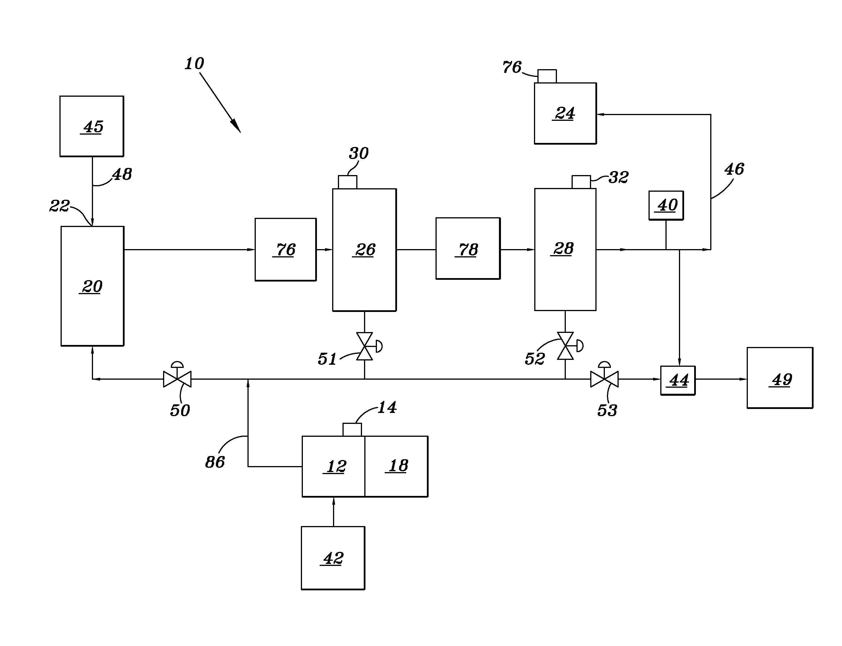
[0027]An embodiment of a variable displacement hydrostatic test system 10 is shown in FIG. 5. It includes a variable displacement hydraulic pump 12 driven by a suitable power source 18 such as an electric motor. Pump 12 is connected to a reservoir 42 containing hydraulic fluid. The pressure of fluid from the hydraulic pump is controlled by a valve 14 in a manner known in the art. Fluid from pump 12 enters intensifying pump 20 via valve 50. Intensifying pump 20 is connected to a source of water, or other suitable intensification fluid 45, via conduit 48.

[0028]Water under pressure exits intensifying pump...

embodiment 60

[0043]An additional embodiment 60 of the invention is shown in FIG. 6. Common elements from the embodiment of FIG. 5 have the same reference numerals.

[0044]In this embodiment the intensifying pump 26 which is of a well-known design includes a plunger 62 located in a hydrostatic chamber 63. A piston 69 is attached to the plunger 62 and is positioned within the hydraulic chamber 61.

[0045]A variable displacement hydraulic pump 12 which is driven by a prime motive source such as an electric motor 18 drives intensifier pump 26 via hydraulic lines 66 and 65 which are connected to the hydraulic power chamber 61 on either side of piston 69.

[0046]Variable displacement pump 12 may be of the type having a variable swash plate the position of which is controlled by a valve 14 in a manner known in the art.

[0047]Water from a reservoir 45 is drawn into hydrostatical chamber 63 through check valve 84 on the intake stroke of plunger 62 and is then directed to the blowout preventer 24 via check valve...


PUM


Abstract

A method and apparatus for testing blowout preventers for leaks involves maintaining a constant pressure in the portion of the blowout preventer to be tested. A sensor is connected to a controller for maintaining a constant pressure within the blowout preventer. Any amount of fluid introduced into or removed from the blowout preventer in order to maintain constant pressure is measured and is an indication of the leak rate in the blowout preventer.

Description

REFERENCE TO RELATED APPLICATIONS[0001]This application claims priority to U.S. Provisional Application Ser. No. 62 / 140,795 filed Mar. 31, 2015, the enter contents of which is incorporated herein by reference thereto.BACKGROUND OF THE INVENTION[0002]1. Field of the Invention[0003]This invention is directed to a method and apparatus for testing hydraulically actuated safely systems such as blowout preventers for leaks.[0004]2. Description of Related Arts Invention[0005]Oil and Gas Exploration risk management includes the ability to control subsurface pressures which may be encounter during drilling operation. The primary mechanism utilized by operators to control downhole pressures is the hydrostatic pressure as a result of the drilling fluid contained within the wellbore. The drilling fluid is engineered and formulated to a density that provides a hydrostatic pressure inside of the wellbore that is greater than the formation pressure being drilled. In the majority of drilling operat...

Claims


Application Information

Patent Timeline
Patent Type & Authority Applications(United States)
IPC IPC(8): G01M3/28E21B33/06E21B47/10
CPCG01M3/2876E21B33/06E21B47/1025E21B47/117
Inventor HILPERT, CLIFFORD L.HILPERT, JEFFREY L.
Owner ENGIP LLC
Why Eureka
Try Eureka