
Method and machine for additive manufacturing reducing risks of powder dissemination during manipulations

a technology of additive manufacturing and manipulation, applied in the field of powder dissemination, can solve the problems of high powder dissemination risk, loss of material, and risk

Active Publication Date: 2020-03-03
COMMISSARIAT A LENERGIE ATOMIQUE ET AUX ENERGIES ALTERNATIVES
View PDF7 Cites 0 Cited by
  • Summary
  • Abstract
  • Description
  • Claims
  • Application Information

AI Technical Summary

Benefits of technology

This approach significantly reduces material loss, composition variations, equipment maintenance, and health risks by containing the powder within a solid block and using sublimation to recover and reuse the material, ensuring safer handling and reduced environmental contamination.

Problems solved by technology

The risk of powder dissemination is high while powder is manipulated during this loading operation.
Such a risk also exists during the final step to unload the manufactured object, surrounded by unbonded powder.
There are several disadvantages with such powder dissemination.
Firstly, powder particles emitted into the atmosphere cause a loss of material, that can be expensive.
Secondly, this loss can cause an unwanted change in the composition.
Powder dissemination can also be the cause of increased equipment maintenance.
These powders deposited in the work environment can carry material that will foul the equipment.
Consequently, specific maintenance actions can become necessary as a result of uncontrolled dissemination.
Finally, dissemination of powder can introduce risks for the health and safety of operators.
For example, inhalation or skin contact with a powder deemed to be dangerous can have effects on health, causing irritations, allergies, disorders of the nervous system and even cancers.
Even powders considered to be inert, in other words with no specific toxicity, can overload the lungs if they are present in large quantities, possibly associated with pulmonary fibrosis.
However, these solutions can be improved and are not necessarily suitable for the field of additive manufacturing by stacking successive layers of powder.

Method used


Image

  • Method and machine for additive manufacturing reducing risks of powder dissemination during manipulations
  • Method and machine for additive manufacturing reducing risks of powder dissemination during manipulations
  • Method and machine for additive manufacturing reducing risks of powder dissemination during manipulations

Examples


Embodiment Construction

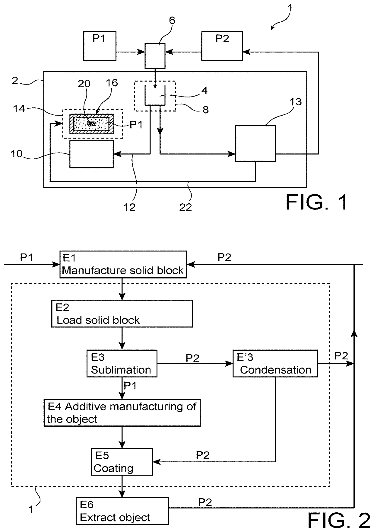
[0064]Firstly with reference to FIG. 1, the figure shows an additive manufacturing machine 1, also called a 3D printing machine, the machine 1 complying with a preferred embodiment of the invention.

[0065]The machine 1 is fitted with an external cover 2, made in a single piece or using several cladding elements added onto each other. These cladding elements 2 also comprise conventional doors (not shown) for loading the powder and for loading the object after manufacturing.

[0066]On FIG. 1, all elements represented inside the space defined by the cladding 2 must be considered as forming an integral part of the machine 1, that can be displaced / handled like a single piece of equipment.

[0067]The machine 1 comprises firstly a loading space 4 capable of containing one or several solid blocks 6, with a shape complementary to the shape of the loading space 4. As a minimum, the solid block 6 must be able to enter the loading space 4.

[0068]Each solid block 6 may be solid or hollow. It contains ...


PUM

PropertyMeasurementUnit
temperatureaaaaaaaaaa
sizeaaaaaaaaaa
sizeaaaaaaaaaa

Abstract

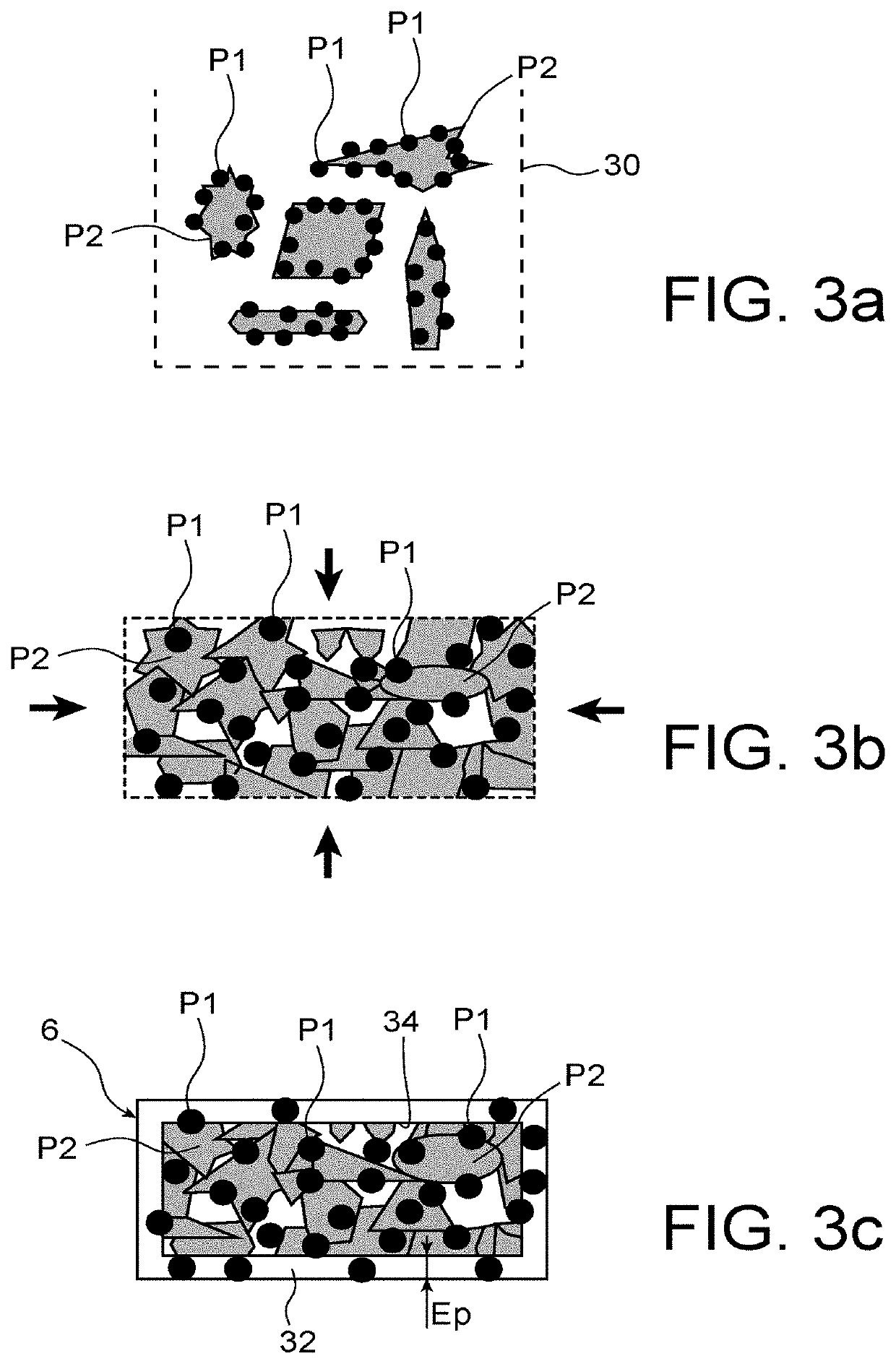
An additive manufacturing method and machine for an object using at least one powder, capable of limiting risks of dissemination of the powder. The method including the following steps in succession: manufacture a solid block starting from the powder and a sublimatable material, load the solid block in a loading space of the machine; sublimate the material present in the solid block and recover the powder; and additive manufacturing of the object by stacking successive layers made using the powder recovered in the previous step.

Description

TECHNICAL FIELD[0001]This invention relates to the field of additive manufacturing of an object, also called 3D printing, by stacking successive layers of powder.[0002]The invention relates particularly to the problem of powder dissemination while it is being manipulated.STATE OF PRIOR ART[0003]In the field of additive manufacturing of an object by stacking successive layers of powder, a first step is usually to load the powder in a special-purpose loading area in the machine used. The risk of powder dissemination is high while powder is manipulated during this loading operation. Such a risk also exists during the final step to unload the manufactured object, surrounded by unbonded powder. There are several disadvantages with such powder dissemination.[0004]Firstly, powder particles emitted into the atmosphere cause a loss of material, that can be expensive. Secondly, this loss can cause an unwanted change in the composition. For example, this is the case when the manipulated powder...

Claims


Application Information

Patent Timeline
Patent Type & Authority Patents(United States)
IPC IPC(8): B22F1/00B29C64/40B22F3/24B22F3/00B22F3/105B29C64/35B28B1/00B29C39/02B33Y70/00B33Y50/02B29C64/386B29C64/153B29C64/20B33Y10/00B33Y30/00B33Y40/00B22F1/14B22F1/145B29K105/00B29K105/16
CPCB22F3/24B29C64/35B29C39/02B33Y40/00B33Y50/02B22F3/1055B33Y30/00B29C64/20B33Y70/00B22F3/005B29C64/386B22F1/0088B22F1/0081B33Y10/00B29C64/153B29C64/40B28B1/001B29K2105/251B29K2105/16B22F2003/1056B22F2003/1059Y02P10/295B22F10/00B22F10/62B22F10/73B22F12/44B22F10/28B22F10/34B22F12/49B22F10/14B22F1/14B22F1/145B29C64/357Y02P10/25
Inventor DELLEA, OLIVIERBERNE, PHILIPPEREVIRAND, PASCAL
Owner COMMISSARIAT A LENERGIE ATOMIQUE ET AUX ENERGIES ALTERNATIVES
Learn More