Systems and methods for converter bed unloading and loading

Inactive Publication Date: 2014-09-11
CYCLONE CATALYST PROPERTIES LLC
View PDF30 Cites 14 Cited by
  • Summary
  • Abstract
  • Description
  • Claims
  • Application Information

AI Technical Summary

Benefits of technology

[0033]One advantage of the present invention is the design and placement of the inline feed inlet 125, which facilitates in the reduction of material loss, such as expensive catalyst material, during material unloading from the converter beds 110. In conventional cyclones, such as that shown as 240 with reference to FIG. 2B, feed inlet 250 is an angled (e.g., 90°) inlet pipe. In such a design, when the material enters the cyclone 240 through the angled inlet 250 it tends to strike a back wall 252 of the angled inlet 250 when entering the cyclone 240, thus causing some of the material (catalyst and rock) to break into smaller pieces. This causes some of the material, the broken up smaller pieces, to be lost by either, or both of, traveling out a cyclone outlet 255 with the air, dust, and other small particles, or it gets screened out as waste material because it is too small to be captured by the larger pore size catalyst or rock screens during screening. This is disadvantageous as the catalyst material is expensive and acid plants want to reduce their material loss as much as possible during the unloading and loading processes. The present invention reduces these material losses by using cyclone 121 with the unique inline feed inlet 125 design and by also the cyclone having an inner chamber wall 215 and outer chamber wall 220, as shown in FIG. 2A. The inline feed inlet 125 design allows the unloaded material, e.g., catalyst and rock, to enter directly into the cyclone 121 inner chamber 205 without having to pass through an angled inlet (such as 250 in FIG. 2B), thus eliminating the issue described above of the material striking the back wall 252 of the angled inlet 250 and potentially breaking up into smaller pieces and being lost as waste material. The inner chamber wall 215 of the present invention is also easily replaceable, so after a period of use if it is damaged due to, for example, the rock material striking it upon entry, it can be replaced without the need to replace the entire cyclone 121. Conventional cyclones, such as 240 in FIG. 2B, used an angled inlet, such as 250 in FIG. 2B, to absorb the impact of incoming rock material thus protecting the inner walls of the cyclone; however, this also resulted in higher losses of catalyst material as explained above. The cyclone 121, having an inner chamber wall 215 that is perforated and outer chamber wall 220 design, further helps maintain the negative pressure needed to sustain the system 100 and remove dust and other fine waste particles to the dust collector 155, while allowing for a dropout region 210 for catalyst and rock material to drop out of the cyclone 121 and onto the screen rig 145, and further eliminates the complicated interlock mechanism used in typical cyclones to allow material to be removed while maintaining the negative pressure needed to sustain such systems.
[0034]FIG. 3, illustrates an example material storage container 175 according to an embodiment of the invention. In one embodiment the material storage container 175 is a substantially square or rectangular container and in one non-limiting example can hold approximately 800-1000 liters of material, such as catalyst, rock, or waste. It should be appreciated that the material storage container may be of other suitable shapes (e.g., barrel, trapezoidal, etc.) and sizes (e.g., able to hold more or less than 800-1000 liter), and the above are just non-limiting examples of the shape and potential capacity of the material storage container 175. The material storage container 175 may include an access port 305, such as a remova

Problems solved by technology

Current systems and methods of unloading and loading material (e.g., catalyst, rock, and/or waste) for use in catalyst converters, such as those used in acid plants (e.g., sulphuric acid plants), have a number of drawbacks that negatively affect cost, efficiencies, environmental risks and safety risks associated with the unloading and loading of catalyst material from the beds of converters in acid plants.
Current systems and methods for unloading and loading catalyst converter beds generate a large amount of waste/material loss, unwanted catalyst and rock dust, and are typically slow and inefficient processes.
The large amount of waste, material lo

Method used


Image

  • Systems and methods for converter bed unloading and loading
  • Systems and methods for converter bed unloading and loading
  • Systems and methods for converter bed unloading and loading

Examples


Embodiment Construction

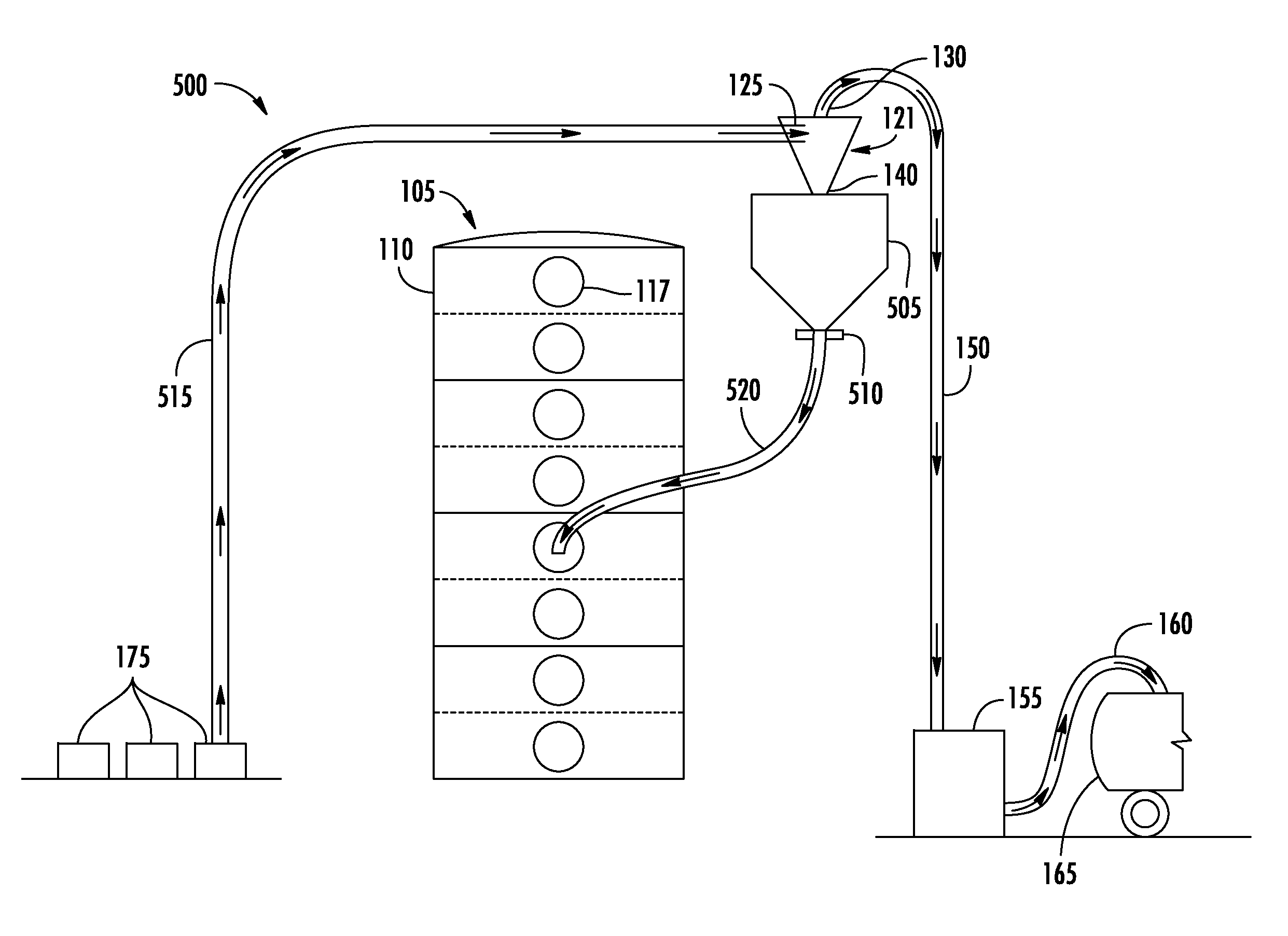
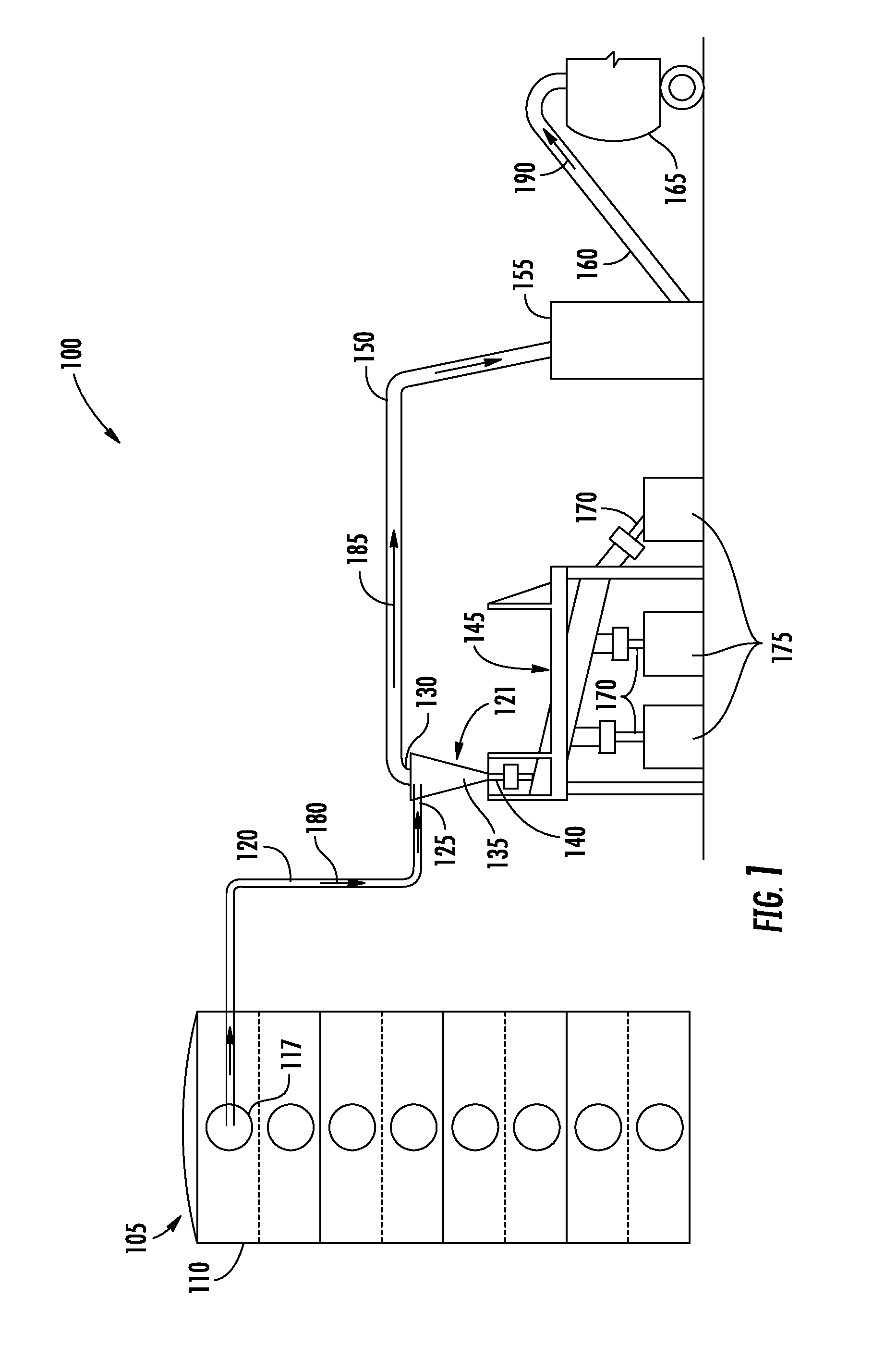
[0022]The present invention relates to systems and methods for catalyst converter bed unloading and loading. The system and method of the invention may be used for unloading, screening and loading material, such as catalyst (for example vanadium pentoxide or other catalyst material) and rock (for example quartz rock), in acid plant converters, for example, sulphuric acid plants.

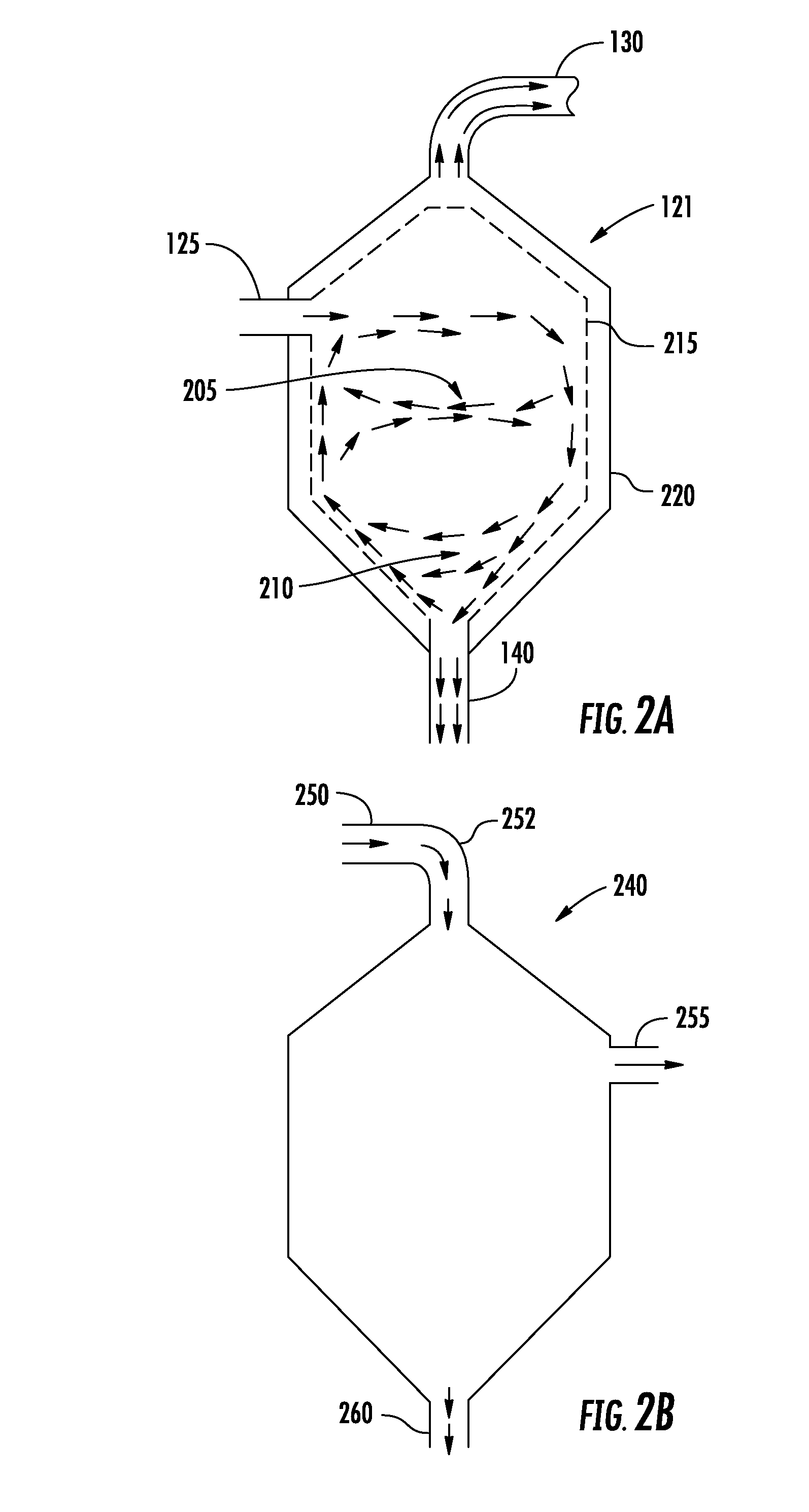
[0023]In one embodiment, a system 100 for vacuum unloading and screening material, such as catalyst, rock, and waste material, from one or more converter beds 110 of a catalyst converter 105. FIGS. 1 and 2A, illustrate an example system 100 and cyclone 121, for unloading material using the cyclone 121 with an inline feed inlet 125. The system 100 may include a vacuum source 165; dust collector 155; a material sorting mechanism 145, cyclone 121; one or more material storage containers 175, feed hose 120, and vacuum hoses 150 and 160.

[0024]The vacuum source 165 may, for example, be a conventional vacuum truck a...


PUM

PropertyMeasurementUnit
Diameteraaaaaaaaaa
Volumeaaaaaaaaaa
Volumeaaaaaaaaaa

Abstract

A system and method for loading material from a converter bed, such as that in a converter of an acid plant, is provided. The system, may include a vacuum source; a dust collector connected to the vacuum source by a first vacuum hose; a cyclone operatively connected to the vacuum source through the dust collector, wherein the cyclone may be connected to the dust collector by a second vacuum hose; a drop-out hopper operatively attached to the cyclone by a valve, such as an air actuated valve, wherein the drop-out hopper includes a first feed hose; and one or more material storage containers operatively associated with the cyclone via a second feed hose. The method of loading material into a converter bed may include providing a system for loading the material in the converter bed; setting up the system; and loading the material into the converter bed.

Description

1 RELATED APPLICATIONS[0001]This patent application is related to and claims priority to U.S. Provisional Patent Application No. 61 / 522,903, filed on Aug. 12, 2011, entitled “Systems, Methods, and Apparatuses for Converter Bed Unloading, Screening, and Loading” the entire disclosure of which is incorporated herein by reference.2 FIELD OF THE INVENTION[0002]The present invention generally relates to systems and methods for unloading and loading of material from catalyst converter beds. In particular, the present invention is directed to vacuum unloading and loading of material from catalyst converter beds, such as those used in acid plants.3 BACKGROUND OF THE INVENTION[0003]Current systems and methods of unloading and loading material (e.g., catalyst, rock, and / or waste) for use in catalyst converters, such as those used in acid plants (e.g., sulphuric acid plants), have a number of drawbacks that negatively affect cost, efficiencies, environmental risks and safety risks associated w...

Claims


Application Information

Patent Timeline
IPC IPC(8): B65G53/60B65D88/26B07B7/00
CPCB65G53/60B65D88/26B07B7/00B04C5/185B01J8/0025B01J8/003B01J8/004B04C5/10B01J2208/00752B01J2208/00761B01D45/12
Inventor WILKINSON, KELLY O.NORVILLE, RICHARD SCOTT
Owner CYCLONE CATALYST PROPERTIES LLC
Why Eureka
Try Eureka