Method for producing electrode plate for battery

a battery and electrode plate technology, applied in the direction of liquid surface applicators, cell components, coatings, etc., can solve the problems of reducing affecting the accuracy of application positions, and affecting the quality of battery electrode plates, so as to reduce the number of steps, improve the efficiency of electrode plate production, and reduce material losses

Inactive Publication Date: 2010-12-30
PANASONIC INTELLECTUAL PROPERTY MANAGEMENT CO LTD
View PDF12 Cites 13 Cited by
  • Summary
  • Abstract
  • Description
  • Claims
  • Application Information

AI Technical Summary

Benefits of technology

[0037]According to the present invention, the step (d) of removing the first non-application portions onto which an electrode active material is not applied, which is provided in connection with carrying out the step (a) of applying the above active material to at least one surface of a long strip-shaped current collector so as to form an active material layer, is carried out simultaneously with the step (c) of cutting the electrode plate precursor that has been rolled to obtain plural strips of electrode plates having a desired width. Thereby, the number of steps can be decreased, and the efficiency of producing electrode plates for batteries can be improved. Further, material losses can be reduced by reducing the material for an electrode plate precursor to be removed in the above step (d). Furthermore, it is possible to reduce the occurrence of quality defects, such as wrinkling and cutting that occur in the step of rolling the electrode plate precursor.

Problems solved by technology

The reason for forming the first non-application portions on both edges of the current collector in the width direction is that there is a limit to the accuracy of an application position since there are cases where a long strip-shaped current collector snakes slightly when applying a paste that is mainly composed of an active material, while feeding the current collector in the longitudinal direction.
Further, there is also a possibility that the paste that has been applied overflows in the width direction due to slump (a state where the shape of applied paste cannot be maintained due to low viscosity or low thixotropy), for instance.
Deformation of the electrode plate precursor in the above rolling step is allowable if the deformation is a uniform deformation in which the thickness is decreased due to uniform extension in the plane direction; however, if it is not, deformation leads to various faults and quality defects.
The occurrence of defects, such as curving and wrinkling, to the electrode plate precursor also causes difficulty when winding the electrode plate precursor after being rolled in a coiled form.
Thus, if there is a difference between pressure applied to the active material applied portion of the electrode plate precursor and that to the non-application portion thereof, difference in extension between these two portions occurs, and such a difference in the extension may cause wrinkling and cutting in the boundary portion between the application portion and the non-application portion.
Further, if a binding force of the active material applied onto the current collector cannot follow the extension of the current collector due to rolling, “cracking” occurs on the surface of the active material layer.
Therefore, production of a battery using such an electrode plate for a battery may result in serious quality defects, particularly in the case of a lithium ion secondary battery.
As described above, an electrode plate precursor is rolled in the state of having both an application portion onto which an active material has been applied and a non-application portion, which causes the occurrence of various defects.
In this case, stress may be concentrated on these portions during rolling, which may cause the occurrence of cutting in the current collector.
Specifically, if the tensile force applied to the current collector is too large, distortion will occur.
If the electrode plate precursor is rolled with the current collector being distorted, there is a high possibility that the distortion will be fixed as wrinkles, which is a plastic deformation.
If the occurred cutting is large, the electrode plate precursor may rupture, and a great production loss is caused in such a case.
In such a case, if rolling is continued using the pressure roller whose circumferential surface has a fragment of the current collector adhering thereto, an accident, such as the pressure roller being damaged, is caused.

Method used


Image

  • Method for producing electrode plate for battery
  • Method for producing electrode plate for battery
  • Method for producing electrode plate for battery

Examples


examples

[0080]Next, the present invention is more specifically described based on Examples and Comparative Examples. It should be noted that the present invention is not limited to these.

examples 5 to 8

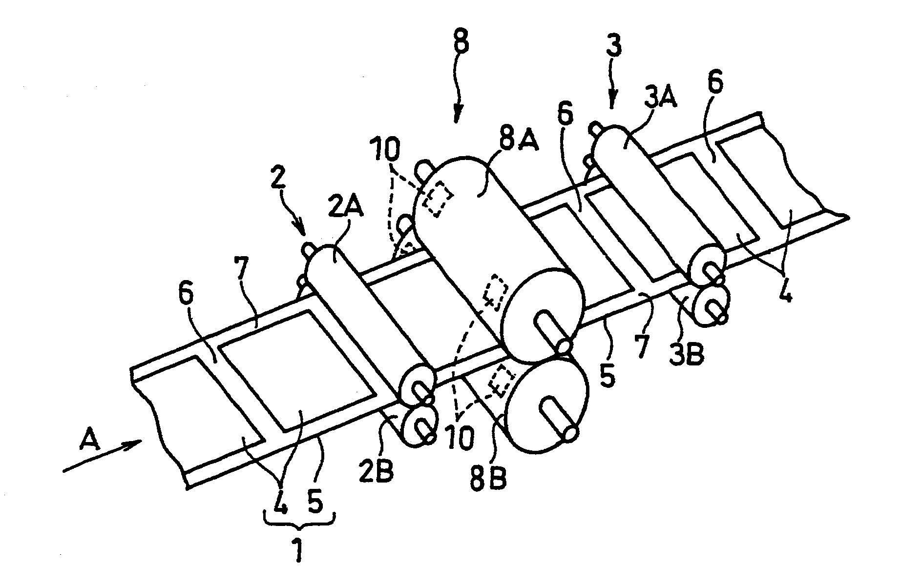
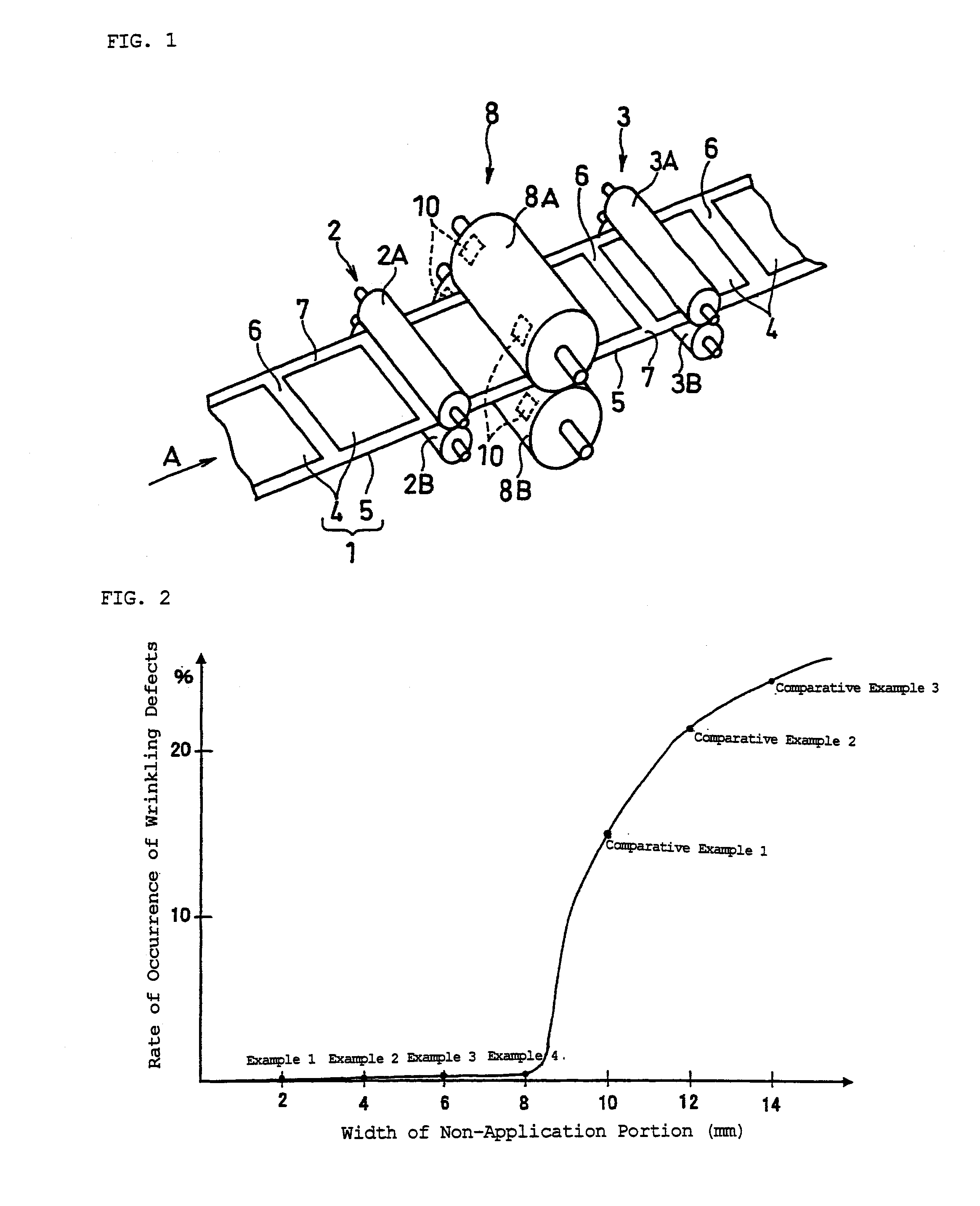
[0098]Using the same material as that in Examples 1 to 4, four types of the first electrode plate precursors 1 were prepared, being provided with the first non-application portions 7 having widths of 2 mm (Example 5), 4 mm (Example 6), 6 mm (Example 7) and 8 mm (Example 8), respectively. Using the rolling apparatus shown in FIG. 1, the first electrode plate precursor 1 having a total thickness of 270 μm was rolled with the rollers 8 so that the total thickness became 210 μm. The rolling rate in this rolling process alone was 23.5%. The first electrode plate precursor 1 that had been wound by a winding reel (not shown) after having been rolled was rolled until the total thickness became 190 μm using the rolling apparatus shown in FIG. 1 again, while unwinding it from the reel with the front and back thereof being reversed. The rolling rate in this rolling process alone was 10.3%. Other than this, a positive electrode plate was produced in the same manner as in Examples 1 to 4. At thi...

examples 9 to 12

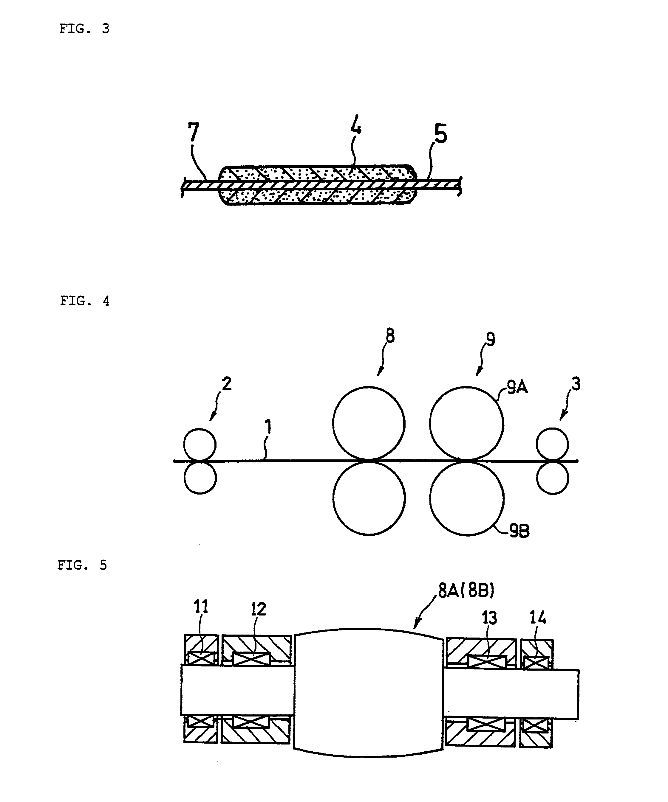
[0102]As shown in FIG. 4, in Examples 9 to 12, a rolling apparatus was used in which downstream pressure rollers 9 constituted by a pair of rollers 9A and 9B have been added and arranged at a position that is downstream of the pressure rollers 8 and upstream of the rear tension rollers 3 of the apparatus shown in FIG. 1. Here, crown rollers (see FIG. 5) were used for the rollers 9A and 9B of the downstream pressure rollers 9.

[0103]Using the same material as that in Examples 1 to 4, four types of the first electrode plate precursors 1 having a total thickness of 270 μm were prepared, being provided with the first non-application portions 7 having widths of 2 mm (Example 9), 4 mm (Example 10), 6 mm (Example 11), and 8 mm (Example 12), respectively. Using the rolling apparatus described above, the first electrode plate precursors 1 were rolled with the pressure rollers 8 until the total thickness thereof became 210 μm (the rolling rate was 23.5%), and thereafter rolled with the downstr...


PUM

PropertyMeasurementUnit
widthaaaaaaaaaa
widthaaaaaaaaaa
widthaaaaaaaaaa

Abstract

A production method of the present invention includes steps of: (a) obtaining a first electrode plate precursor 1 by applying an electrode active material onto at least one of surfaces of a long strip-shaped current collector so as to form an active material layer, (b) rolling an electrode plate precursor so that the active material layer has a predetermined thickness, and (c) obtaining plural strips of electrode plates by cutting the rolled electrode plate precursor to a desired width. In the step (a), non-application portions onto which an active material is not applied are formed on both edges of the electrode plate precursor in the width direction. The step (d) of removing the non-application portions is carried out simultaneously with the step (c). Accordingly, it is possible to improve production efficiency and reduce material losses by decreasing quality defects that occur in the step of rolling the electrode plate precursor.

Description

TECHNICAL FIELD[0001]The present invention relates to a method for producing an electrode plate for a battery, and more particularly to an improvement in a method for producing an electrode plate for a battery in which an active material is applied onto a strip-shaped current collector, and the current collector is cut to a desired size.BACKGROUND ART[0002]In recent years, electric devices, such as audiovisual devices, personal computers, and portable communication devices, have become portable and cordless at an increasing rate. Conventionally, aqueous batteries, such as nickel-cadmium batteries and nickel-metal hydride batteries, have been mainly used as power sources for driving such electric devices. However, in recent years, for the batteries used as these power sources, non-aqueous electrolyte batteries, which are represented by lithium ion secondary batteries that can be quickly charged, and that have both a high volume energy density and a high weight energy density, are bec...

Claims


Application Information

Patent Timeline
Patent Type & Authority Applications(United States)
IPC IPC(8): B05D5/12H01M4/04H01M4/139H01M10/0525
CPCH01M4/0404Y02E60/122H01M10/0525H01M4/0409Y02E60/10
Inventor SHIMIZU, KYOUSHIGEOSHIMA, KENICHIHORI, HIDEO
Owner PANASONIC INTELLECTUAL PROPERTY MANAGEMENT CO LTD
Why Eureka
Try Eureka