Sliding device

Inactive Publication Date: 2005-03-15
BURTON USA
View PDF187 Cites 20 Cited by
  • Summary
  • Abstract
  • Description
  • Claims
  • Application Information

AI Technical Summary

Benefits of technology

In another illustrative embodiment, the deck, runner and/or a spacer may be arranged so that at least a portion of either the deck or the runner can move longitudinally relative to the other. Thus, a rigid attachment between the deck and runner may be maintained to prevent relative pivoting of the deck and runner (at least about a longitudinal axis), while

Problems solved by technology

However, the bindings prevent the rider from freely moving his or her feet on the board, which in

Method used


Image

  • Sliding device
  • Sliding device
  • Sliding device

Examples


Example

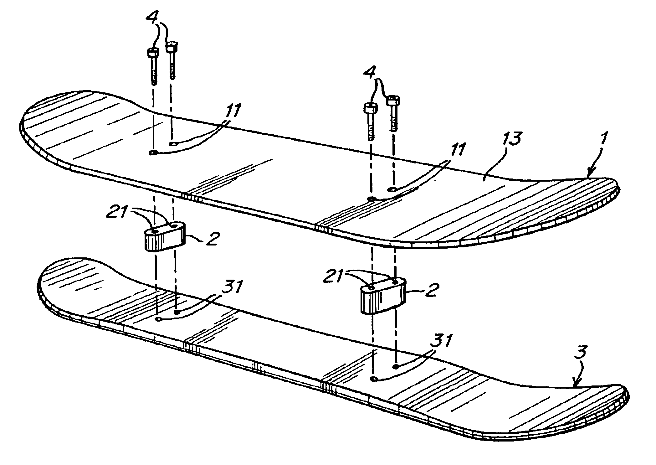
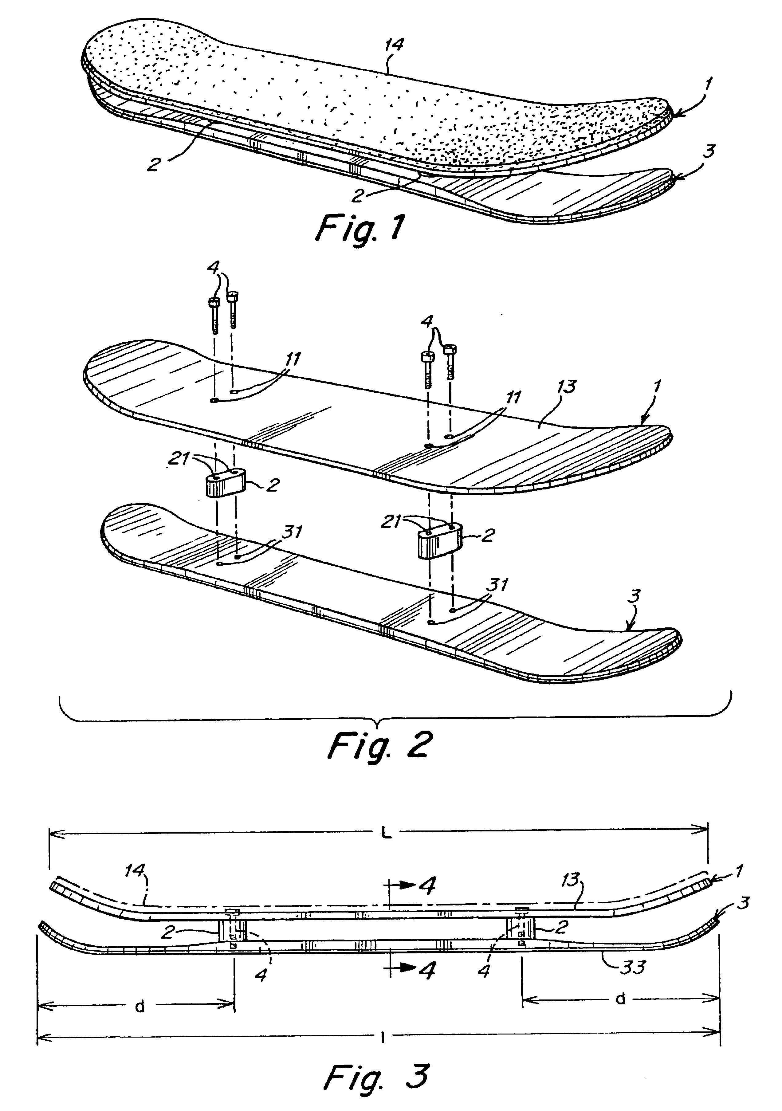
Illustrative embodiments of the invention provide a sliding device that may be ridden by standing on the deck in much the same way as a typical skateboard. Although for clarity and ease of reference a sliding device in accordance with the invention is described in connection with a “snowdeck” for use on snow, the sliding device may be used on other surfaces, such as ice, sand, plastic, metal, and so on.

In one embodiment, the snowdeck has a bi-level design such that the rider stands in an upright position on a deck that is vertically spaced from, and attached to, a sliding portion, or runner, that contacts the sliding surface. Thus, for example, the snowdeck may be turned on the sliding surface, such as a snow-covered slope, by tilting the deck with the feet, somewhat similar to that in skateboarding. The deck can be tilted and the snowdeck steered by the rider shifting weight between her toes and heels on the deck. By tilting the snowdeck to one side or the other, the rider can caus...


PUM


Abstract

A sliding device provides a binding-free apparatus suitable for trick and other riding on snow, sand, ice and other surfaces. An elongated deck to support the rider is elevated from and attached to an elongated runner, which provides a surface that slides on the snow, sand, etc. The runner may be made more narrow than the deck to provide leverage for the rider to tilt the device onto an edge of the runner to steer the device. The device may not have any defined front or back portion and thus be adapted for riding in either direction.

Description

FIELD OF THE INVENTIONThis invention relates to sliding devices for use on snow, ice, sand or other surfaces.BACKGROUND OF THE INVENTIONThere has been a desire amongst snowsports enthusiasts to perform tricks similar to those performed with a typical skateboard. For example, snowboards have been used to perform skateboard-type tricks, such as half pipe and quarter pipe maneuvers and the like. Bindings fixed in place on the snowboard secure the rider's feet so that the rider can maneuver the board, e.g., tilt the board on edge to execute a turn. However, the bindings prevent the rider from freely moving his or her feet on the board, which in turn prevents the rider from performing some tricks, such as those common among skateboard riders.SUMMARY OF THE INVENTIONIn an illustrative embodiment, a sliding device in accordance with the invention provides a rider with the ability to perform skateboard-like tricks on snow, sand, ice, metal, plastic or other sliding surfaces. For example, th...

Claims


Application Information

Patent Timeline
IPC IPC(8): A63C5/00A63C5/03
CPCA63C5/03A63C5/033A63C2203/46
Inventor BARBIERI, G. SCOTTCAPPOZZI, MATT
Owner BURTON USA
Why Eureka
Try Eureka