Apparatus for connecting fluid conduits

a fluid conduit and apparatus technology, applied in the direction of fluid pressure sealing joints, joints with sealing surfaces, sleeve/socket joints, etc., can solve the problems of increasing the stress on the entire network, increasing the cost of the entire network, and heavy flanges, etc., to reduce the longitudinal force and reduce the clamping force

Inactive Publication Date: 2005-03-15
STRONSKI DALE
View PDF8 Cites 0 Cited by
  • Summary
  • Abstract
  • Description
  • Claims
  • Application Information

AI Technical Summary

Benefits of technology

It is an object of the present invention to provide an apparatus for connecting conduits together, or to other conduit network components that overcomes disadvantages of the prior art connections. It is a further object of the present invention to provide such an apparatus that requires reduced clamping forces to connect the conduits together. It is a further object of the present invention to provide such an apparatus that reduces longitudinal forces exerted on connected conduits.
Installation is simplified since the high torque and even clamping force required by conventional connections is not required by the apparatus of the invention. Stress on the conduit network is reduced since clamping forces and the resulting longitudinal forces exerted on the conduits are reduced. Installation and design are simplified.

Problems solved by technology

The flanges must be strong enough to resist distortion under the clamping forces, and as a result such flanges are commonly heavy, costly, and cumbersome, especially for high pressure conduits.
These forces are transferred through the conduit network from each such connection, causing stress on the entire network.

Method used


Image

  • Apparatus for connecting fluid conduits
  • Apparatus for connecting fluid conduits
  • Apparatus for connecting fluid conduits

Examples


Embodiment Construction

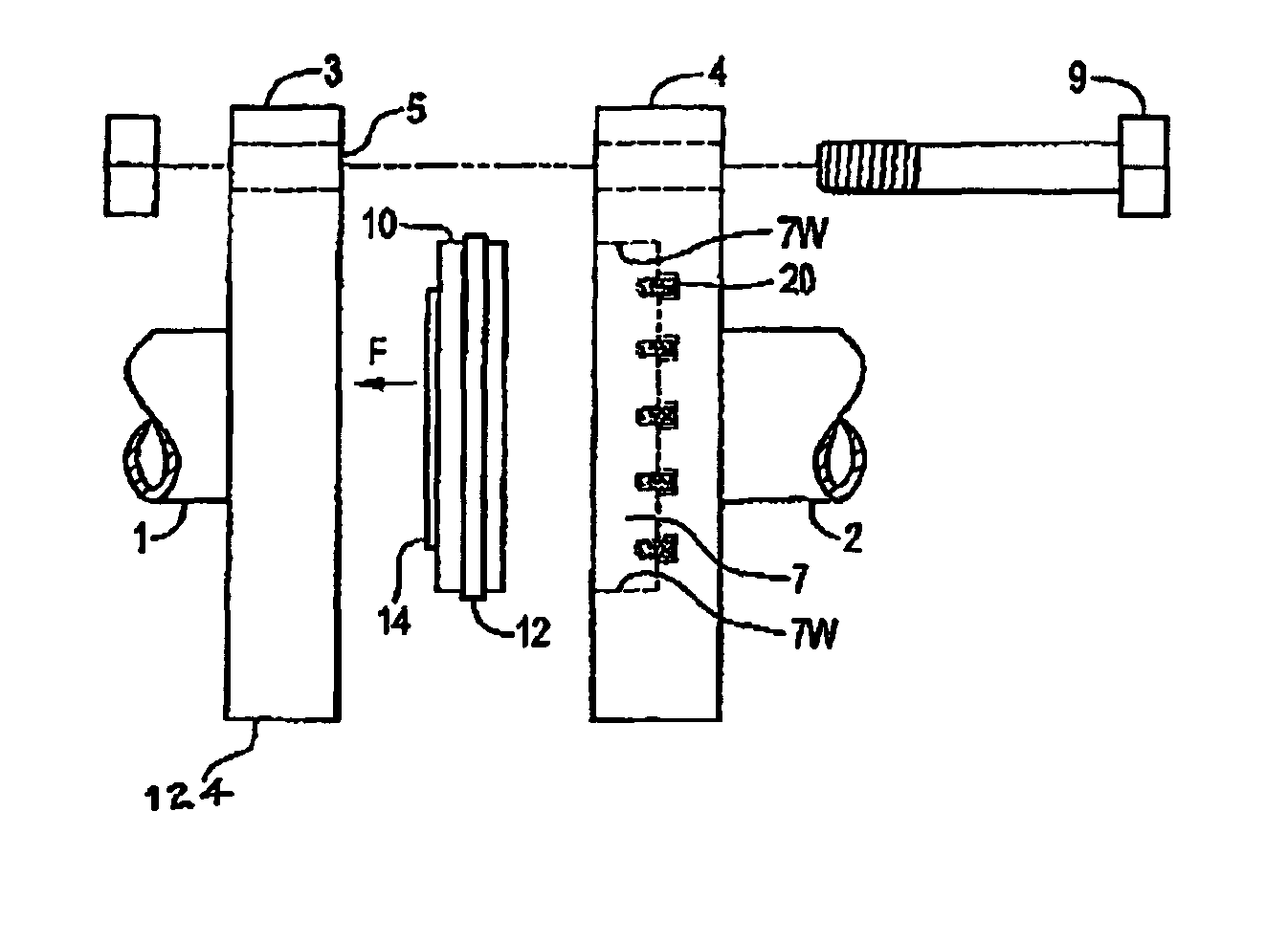
FIG. 1 illustrates an apparatus of the present invention for connecting conduits 1 and 2 to carry a fluid under pressure. The apparatus comprises a first flange, illustrated as flat flange 3 with a flat face 5 attached around an open end of the first conduit 1. A pocket flange 4 is attached around an open end of the second conduit 2 and has a pocket face 11 that defines a pocket 7. The same connection can be made where one of the flanges 3, 4 is attached to a conduit that is incorporated in a T-fitting, an elbow, or any like component of a conduit network.

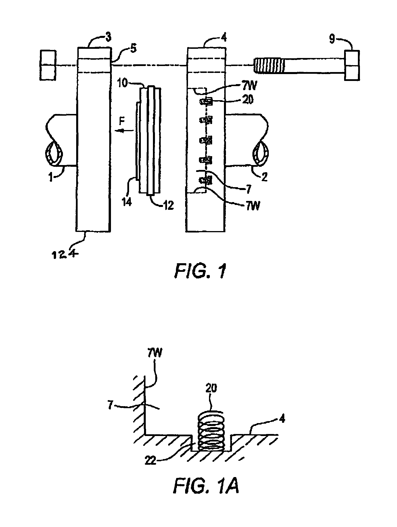
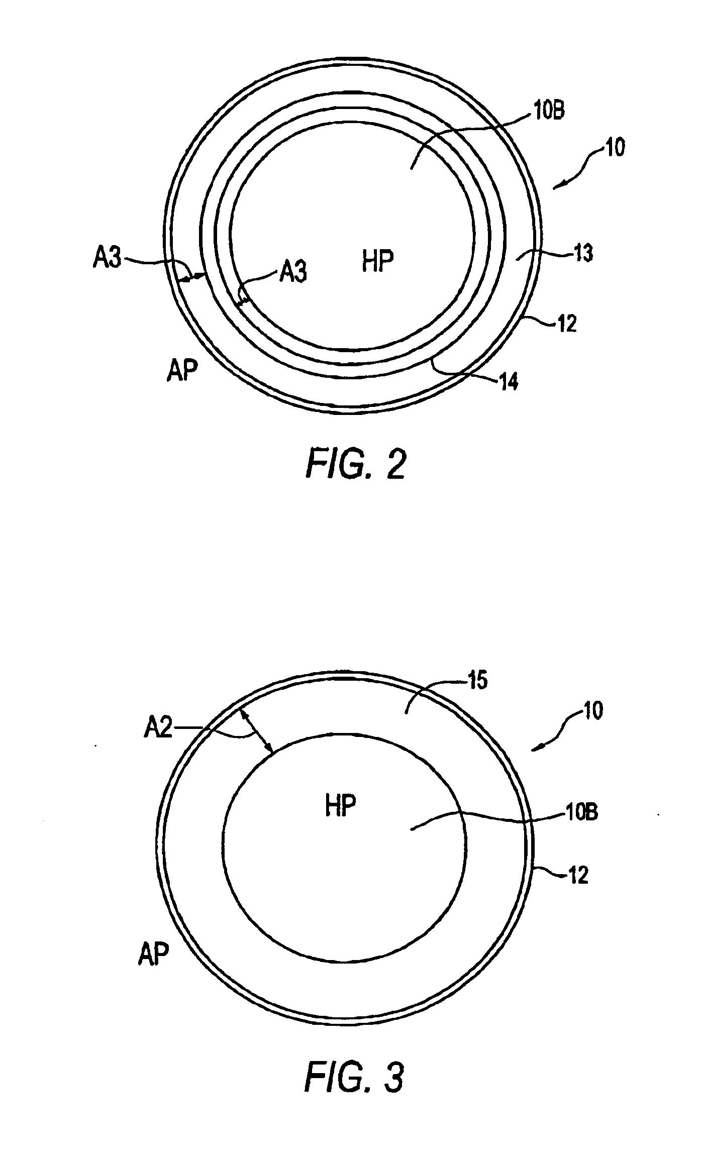
The first face 5 is adapted to be fastened to the pocket face 11 with bolts 9 or the like such that the first face is 5 substantially perpendicular to walls 7W of the pocket 7 and adjacent to an open end of the pocket 7. A threaded union, or similar known mechanism for holding the flanges together could be used as well. A gasket member 10 is slidingly engaged in the pocket 7 and defines a passageway through a central portion thereo...


PUM


Abstract

An apparatus for connecting first and second conduits to carry a fluid under pressure comprises a first face attached around an open end of the first conduit and a pocket face attached around an open end of the second conduit and defining a pocket. The first face is fastened to the pocket face such that the first face is substantially perpendicular to walls of the pocket and adjacent to an open end of the pocket. A gasket member is slidingly engaged in the pocket and defines a passageway through a central portion thereof. The gasket member has a gasket face adjacent and substantially parallel to the first face and an opposite pressure face inside the pocket. A bias element exert a bias force on the gasket member toward the first face and a pocket seal seals an outer periphery of the gasket member to the walls of the pocket. A main gasket is located between the gasket face of the gasket member and the first face, and the pressure face of the gasket member is exposed to fluid carried by the conduits and has an area that is greater than an area of the gasket face between the main gasket and the passageway through the gasket member. The higher the pressure inside the conduits the greater the force that is exerted on the main gasket, sealing the connection.

Description

This application claims priority to and benefit of, currently Canadian Patent Application Serial Number 2,439,323, filed on Sep. 3, 2003.TECHNICAL FIELDThis invention is in the field of fluid conduits such as are used to carry liquids and gases, and in particular an apparatus for connecting such conduits together or to various fittings in a conduit network.BACKGROUND OF THE INVENTIONSections of fluid conduit must be connected together, or to other fittings in a conduit network to carry gases and liquids without leaking from the network. The fluid pressure varies from low pressure lines, such as sewage lines where the pressure is essentially atmospheric pressure, to higher pressure water lines and the like, up to very high pressure industrial lines where the pressure is 10,000 pounds per square inch (psi) or more.Conventional conduit connections are made using a gasket that is essentially clamped and squeezed between hollow members attached to each conduit. The clamping force is exer...

Claims


Application Information

Patent Timeline
Patent Type & Authority Patents(United States)
IPC IPC(8): F16L23/00F16L23/18
CPCF16L23/18
Inventor STRONSKI, DALE
Owner STRONSKI DALE
Why Eureka
Try Eureka