

Controlled face dragging in solid models
a solid model and control technology, applied in the field of three-dimensional modeling systems, can solve the problems of invalid adjacent faces (i.e., drags), and users cannot control how adjacent faces should be adjusted
- Summary
- Abstract
- Description
- Claims
- Application Information
AI Technical Summary
Benefits of technology
Problems solved by technology
Method used
Image

Examples
Embodiment Construction
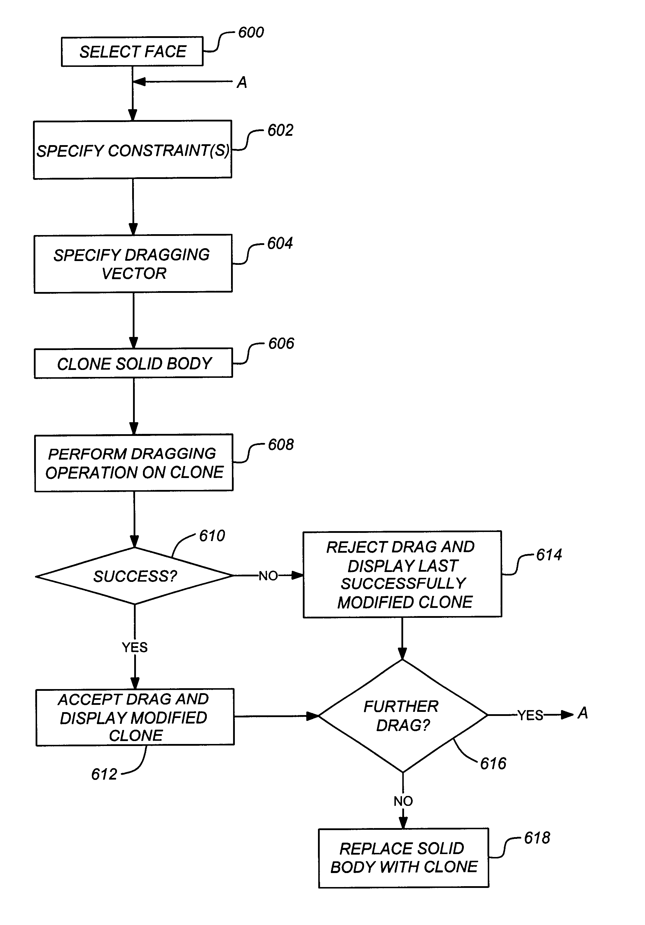
ing operation in accordance with one or more embodiments of the invention;
[0026]FIG. 8 illustrates a cloned solid body created during a repositioning operation in accordance with one or more embodiments of the invention;
[0027]FIG. 9 is a flow chart illustrating the details a controlled face dragging operation in accordance with one or more embodiments of the invention;
[0028]FIGS. 10A and 10B illustrate an example of the result of the adjustment of the vertices and planes of side faces in a more complex solid body where the side faces contain holes, cuts, and ribs in accordance with one or more embodiments of the invention; and
[0029]FIG. 11 illustrates how a new plane of a side face is determined in accordance with one or more embodiments of the invention.
DETAILED DESCRIPTION OF THE PREFERRED EMBODIMENTS
[0030]In the following description, reference is made to the accompanying drawings which form a part hereof, and which is shown, by way of illustration, several embodiments of the pre...
PUM
 Abstract
Description
Claims
Application Information