Immersion photolithography system and method using microchannel nozzles

a technology of immersion photolithography and microchannel nozzles, which is applied in the direction of printing, instruments, electrical equipment, etc., can solve the problems of optical distortion, optical lithography limit, and commercialization of immersion photolithographic systems

Inactive Publication Date: 2005-03-15
ASML HLDG NV
View PDF6 Cites 419 Cited by
  • Summary
  • Abstract
  • Description
  • Claims
  • Application Information

AI Technical Summary

Benefits of technology

The present invention is directed to an immersion photolithography system with a near-uniform velocity profile of th...

Problems solved by technology

The practical limits of optical lithography assume that the medium through which imaging is occurring is air.
However, despite the promise of immersion photolithography, a number of problems remain, which have so far precluded commercialization of immersion photolithographic systems.
These problems include optical distortions.
For example, during immersion lithogr...

Method used


Image

  • Immersion photolithography system and method using microchannel nozzles
  • Immersion photolithography system and method using microchannel nozzles
  • Immersion photolithography system and method using microchannel nozzles

Examples


Embodiment Construction

Reference will now be made in detail to the embodiments of the present invention, examples of which are illustrated in the accompanying drawings.

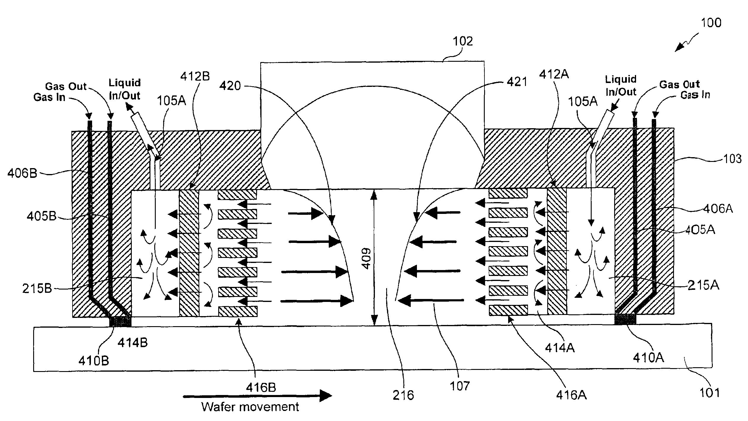
One major problem in immersion photolithography is the non-uniformity of the liquid flow, particularly its gradient in the vertical direction. The non-uniformity is due primarily to the fact that near a moving surface, the liquid is in contact with that surface (e.g., a surface of a wafer). For example, during scanning, the wafer moves relative to the exposure system, creating a “dragging effect” near its surface. Thus, the laws of fluid dynamics dictate that the fluid velocity relative to the wafer surface is zero in those areas (or at least close to zero), while fluid velocity is maximum further away from the wafer surface. Similarly, the fluid velocity relative to the bottom surface of the lens is zero. These fluid velocity variations are known as “boundary layer” velocity profiles. The combination of these effects produces a shearing fo...


PUM


Abstract

A liquid immersion photolithography system includes an exposure system that exposes a substrate with electromagnetic radiation and includes a projection optical system that focuses the electromagnetic radiation on the substrate. A liquid supply system provides liquid flow between the projection optical system and the substrate. An optional plurality of micronozzles are arranged around the periphery of one side of the projection optical system so as to provide a substantially uniform velocity distribution of the liquid flow in an area where the substrate is being exposed.

Description

BACKGROUND OF THE INVENTION1. Field of the InventionThe present invention relates to liquid immersion photolithography, and more particularly, to a method and a system for controlling velocity profile of liquid flow in an immersion photolithographic system.2. Description of the Related ArtThe practical limits of optical lithography assume that the medium through which imaging is occurring is air. This practical limit is defined by the effective wavelength equation Λeff=λ2·n·NA,where λ is the wavelength of incident light, NA is the numerical aperture of the projection optical system, and n is the index of refraction of the medium. Now, by introducing a liquid (instead of the air) between a last lens element of the projection optical system and a wafer being imaged, the refractive index changes (increases), thereby enabling enhanced resolution by lowering the effective wavelength of the light source. Lowering a light source's wavelength automatically enables finer resolution of smalle...

Claims


Application Information

Patent Timeline
IPC IPC(8): G03F7/20H01L21/00H01L21/02H01L21/027
CPCG03F7/70341G03F7/709G03F7/70358G03F7/20H01L21/027
Inventor VOGEL, HERMANSIMON, KLAUSDERKSEN, ANTONIUS THEODORUS ANNA MARIA
Owner ASML HLDG NV
Why Eureka
Try Eureka