
Circuit and method for controlling the gain of an amplifier based on the sum of samples of the amplified signal

a technology of amplified signal and amplifier gain, applied in the field of electronic circuits, can solve the problems of limiting the total number of data bits that the disk b>16/b> can store, reading stored data inaccurately, etc., and achieves the effect of promoting faster settling of amplifier gain and higher data-storage density

Inactive Publication Date: 2005-03-15
STMICROELECTRONICS SRL
View PDF14 Cites 23 Cited by
  • Summary
  • Abstract
  • Description
  • Claims
  • Application Information

AI Technical Summary

Benefits of technology

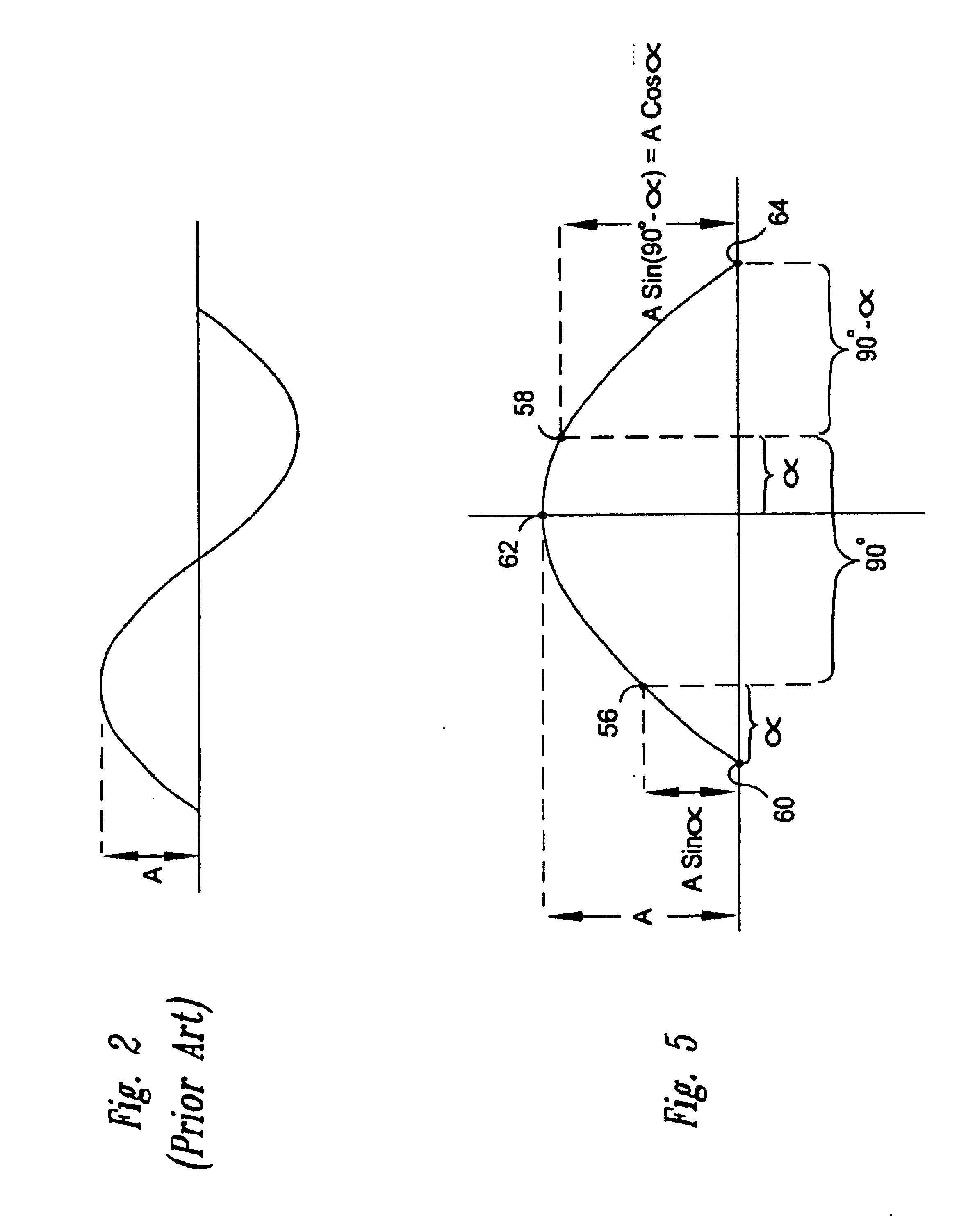
Such a circuit can provide an initial, coarse gain adjustment to a read-signal amplifier in a disk-drive read channel. Compared to prior read channels, this initial adjustment promotes faster settling of the amplifier gain at the beginning of a data sector. This faster settling allows the data sector to have a shorter preamble, and thus allows the disk to have a higher data-storage density. Furthermore, because the phase angle between the sample clock and the preamble sinusoid may be unknown at the beginning of the data sector, the circuit can determine the initial gain adjustment independent of this phase angle.

Problems solved by technology

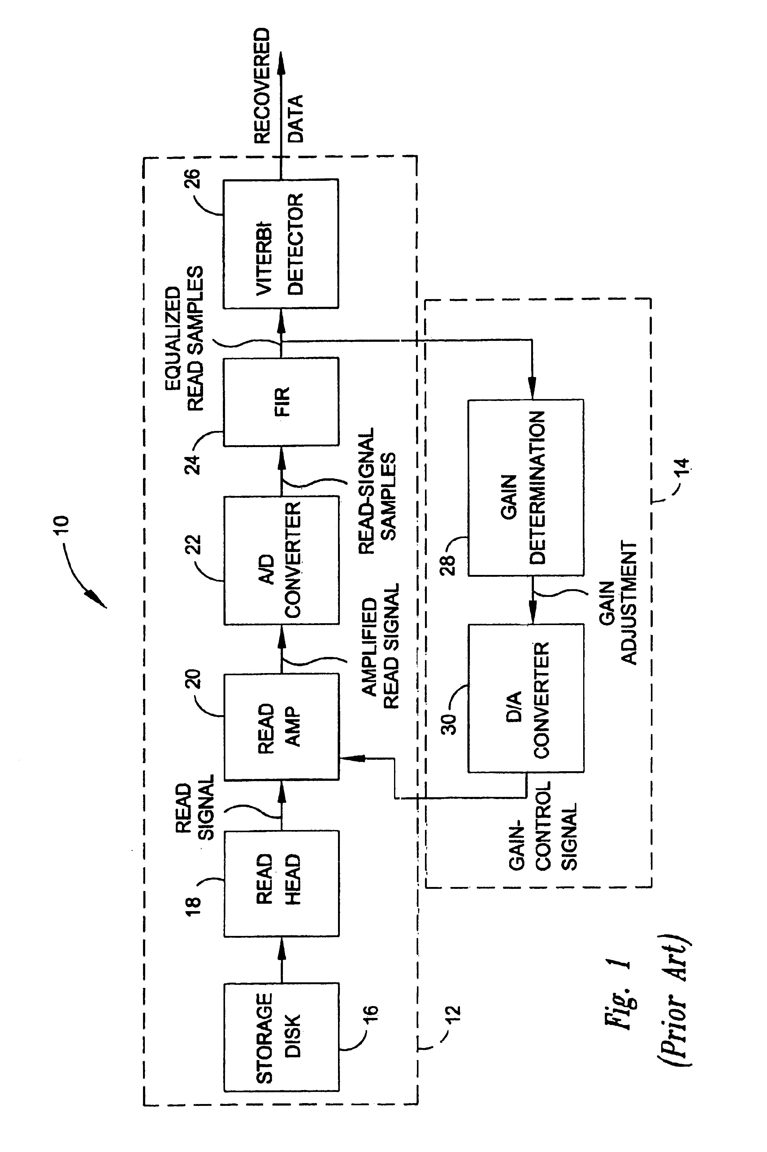
But if the preamble is too short, then the read channel 10 may calibrate itself improperly, and thus may read the stored data inaccurately.
Unfortunately, the gain-control circuit 14 often limits the storage density of the disk 16.
Unfortunately, this requirement limits the number of data bits that each data sector can store, and thus limits the total number of data bits that the disk 16 can store.

Method used


Image

  • Circuit and method for controlling the gain of an amplifier based on the sum of samples of the amplified signal
  • Circuit and method for controlling the gain of an amplifier based on the sum of samples of the amplified signal
  • Circuit and method for controlling the gain of an amplifier based on the sum of samples of the amplified signal

Examples


Embodiment Construction

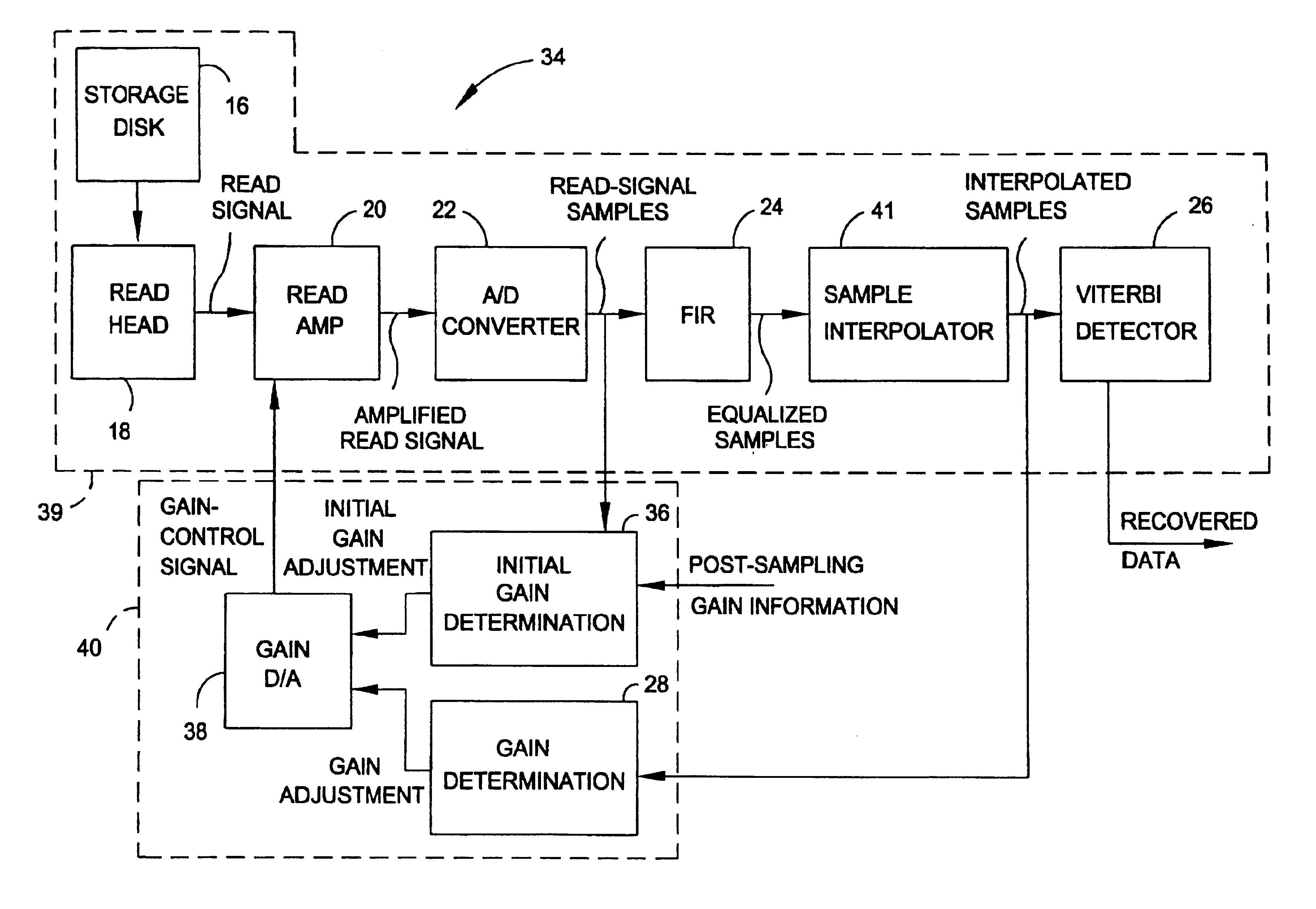
FIG. 3 is a block diagram of a read channel 34 according to an embodiment of the invention. The read channel 34 is similar the to read channel 10 of FIG. 1; therefore, like numerals reference like components in FIGS. 1 and 3. But unlike the read channel 10, the read channel 34 includes an initial-gain-determination circuit 36, which provides an initial, coarse gain adjustment to the read amplifier 20 via a conventional D / A converter 38. Compared to the read channel 10, this initial adjustment promotes faster settling of the amplifier gain at the beginning of each data sector. This faster settling allows each data sector to store a shorter preamble, and thus allows the disk 16 to have a higher data-storage density.

More specifically, the read channel 34 includes a read path 39, which is similar to the read path 12 of FIG. 1 except that it uses digital timing recovery, and thus includes a sample interpolator 41 coupled between the FIR filter 24 and the Viterbi detector 26. Briefly, dig...


PUM

PropertyMeasurementUnit
phase angleaaaaaaaaaa
lengthaaaaaaaaaa
data-storage densityaaaaaaaaaa

Abstract

A circuit controls the gain of an amplifier that amplifies an information signal. The circuit includes a buffer for storing first and second samples of the amplified information signal, and a gain-determination circuit coupled to the buffer. The gain-determination circuit generates a gain adjustment based on the sum of the first and second samples, the gain adjustment causing the amplifier to change the amplitude of the amplified information signal to or toward a predetermined amplitude. Such a circuit can provide an initial, coarse gain adjustment to a read-signal amplifier in a disk-drive read channel. Compared to prior read channels, this initial adjustment promotes faster settling of the amplifier gain at the beginning of a data sector. This faster settling allows the data sector to have a shorter preamble, and thus allows the disk to have a higher data-storage density. Furthermore, because the phase angle between the sample clock and the preamble sinusoid may be unknown at the beginning of the data sector, the circuit can determine the initial gain adjustment independent of this phase angle.

Description

TECHNICAL FIELD OF THE INVENTIONThe invention relates generally to electronic circuits, and more particularly to a circuit and method for controlling the gain of an amplifier based on the sum of samples of the amplified signal. In one application, a circuit according to the invention provides an initial gain adjustment to a read-signal amplifier in a disk-drive read channel. This initial adjustment allows the amplifier gain-adjust circuitry to more quickly determine and set the proper amplifier gain at the beginning of a disk data sector. This faster determination and setting allows a reduction in the length of the data-sector preamble, and thus allows an increase in the disk data-storage density. Furthermore, because the phase angle between the sample clock and the preamble sinusoid may be unknown at the beginning of the data sector, the circuit can determine the initial gain adjustment independent of this phase angle.BACKGROUND OF THE INVENTIONFIG. 1 is a block diagram of a conven...

Claims


Application Information

Patent Timeline
Patent Type & Authority Patents(United States)
IPC IPC(8): G11B20/10G11B5/012H03G3/20H03M1/18
CPCG11B20/10037G11B20/10027G11B20/10009G11B5/012
Inventor OZDEMIR, HAKAN
Owner STMICROELECTRONICS SRL
Learn More