
Closing cap for infusion and transfusion bottles

a technology for infusion and transfusion bottles, applied in the direction of bottles, needles, containers, etc., can solve the problems of axially oriented weakening, cracking, and cracking, and achieve the effect of facilitating bottle opening and increasing the level of security

Inactive Publication Date: 2005-03-22
HELVOET PHARM BELGIUM NV
View PDF15 Cites 30 Cited by
  • Summary
  • Abstract
  • Description
  • Claims
  • Application Information

AI Technical Summary

Benefits of technology

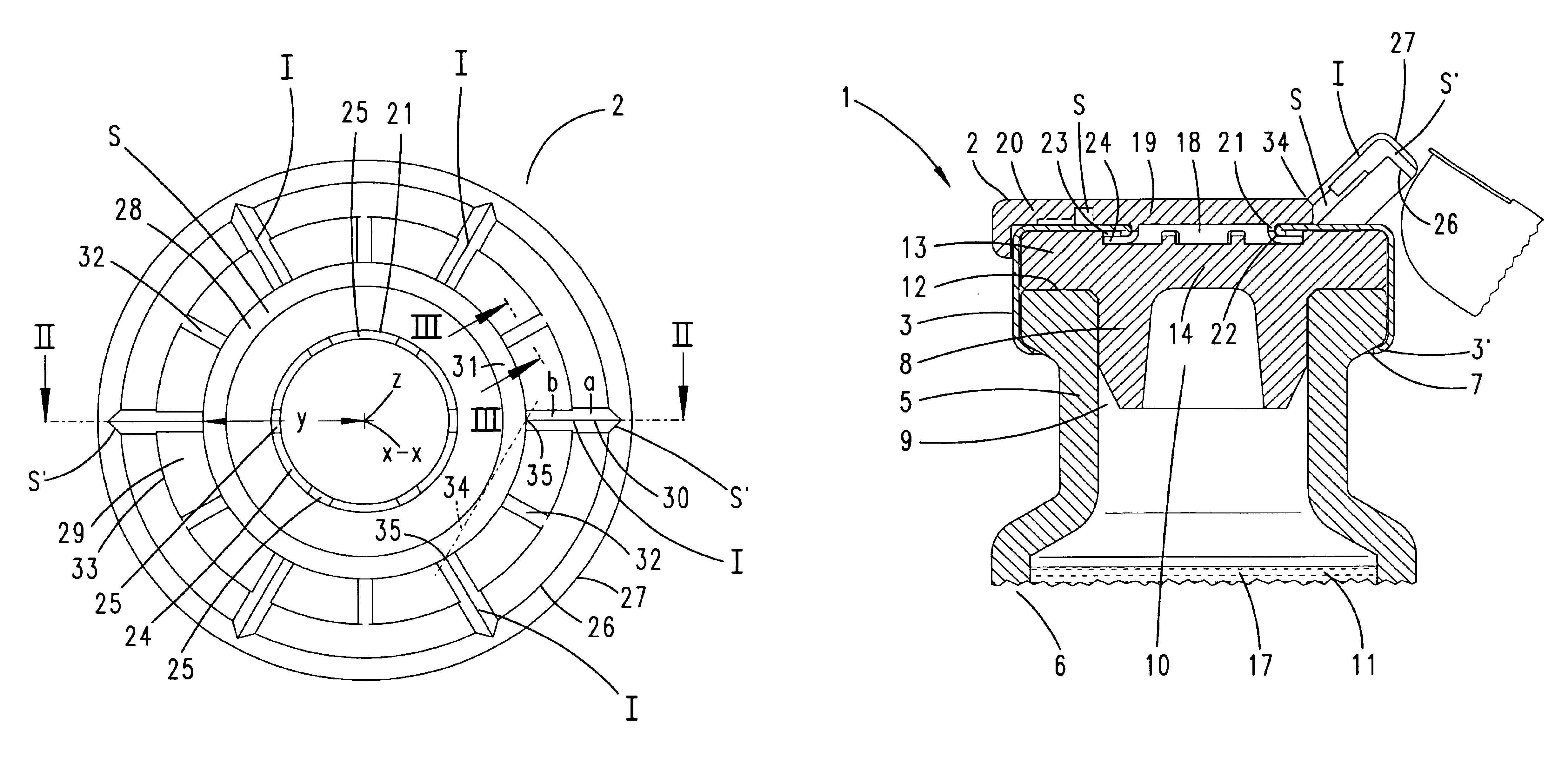
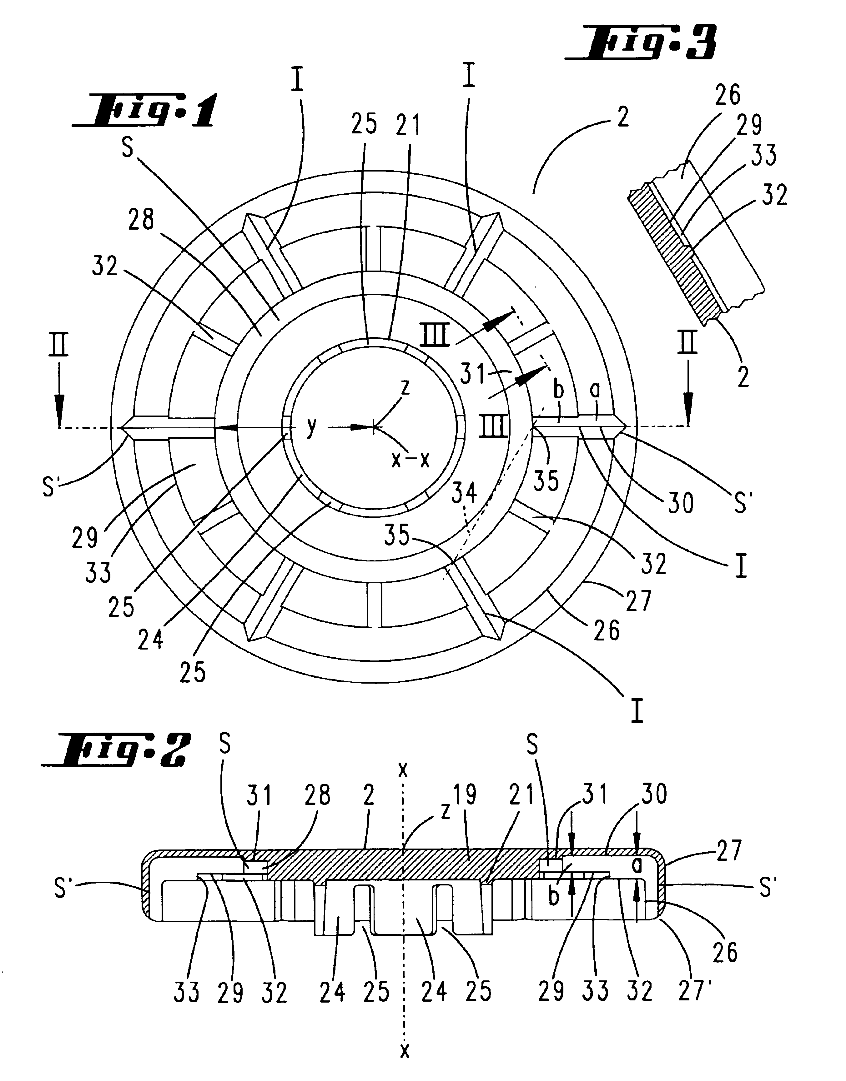
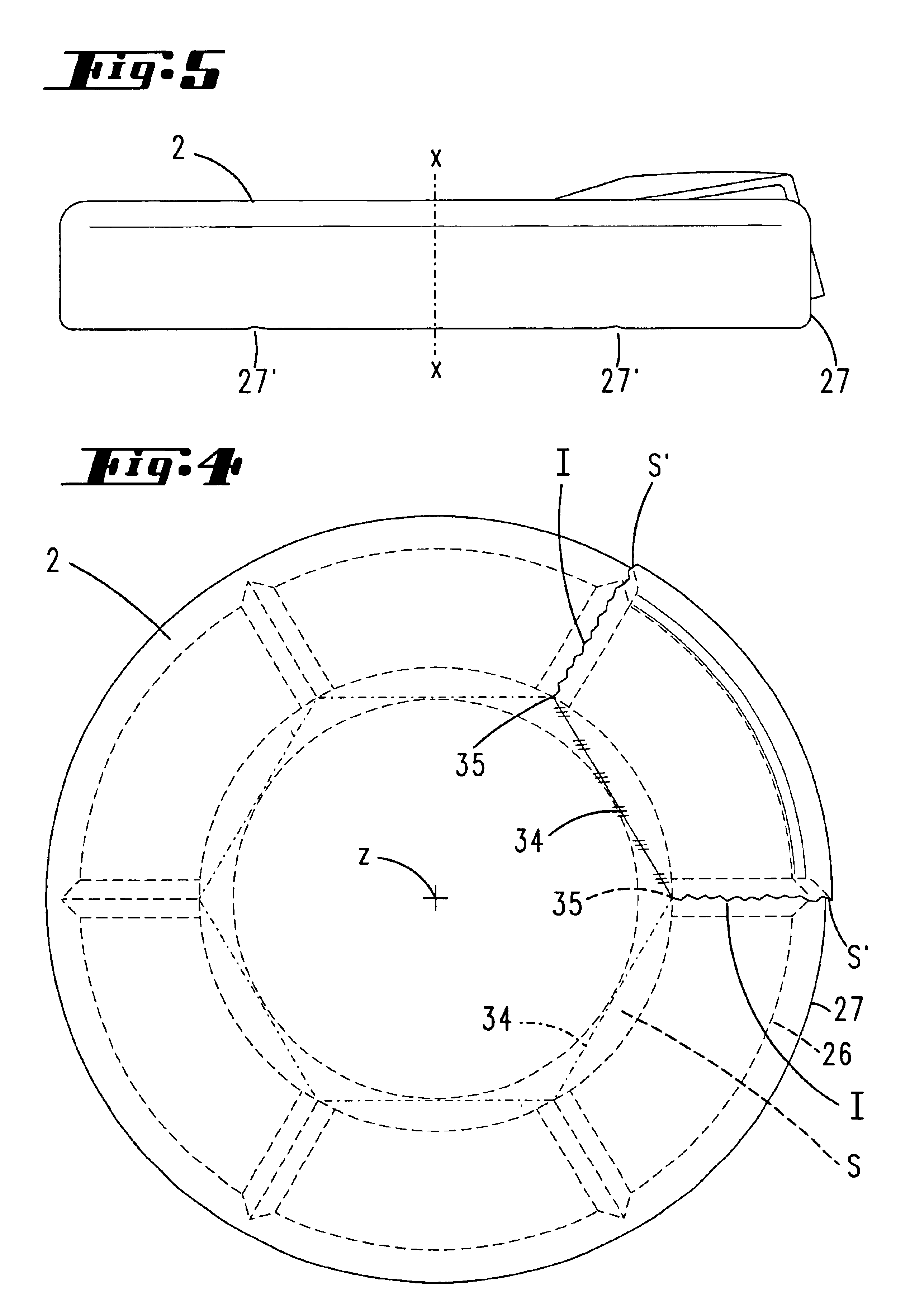
A configuration of this type produces a closure cap of the generic type with an increased level of security. Use leaves behind clear indications. Reuse of the closure cap for tampering purposes is virtually ruled out. Protection against tampering with medicaments of this type is becoming increasingly important. The construction according to the invention leads to a bending characteristic which goes as far as breaking. The circumferential weakening which runs around a center point not only leads to a breaking crack with regard to the desired bending lines, but also to a white breakage indicator in the plastic cover, on account of the stipulated geometrically arched bending axis, which, however, in reality develops transversely to the upward folding direction of the bent part of the plastic cover. The visible feature is retained. The desired effect is further enhanced by the fact that the radially running desired bending line continues, on the outer edge side, into an axial weakening of the plastic cover, the desired bending line being formed into the axial inner surface of the plastic cover. This axially oriented weakening occurs as an additional breaking crack. Forming the weakening at the inner surface makes the corresponding tamper-proofing means virtually invisible from the outside. On the other hand, the breaking crack occurs as soon as it is attempted to open the cap. Furthermore, the invention proposes that the material thinning is greater in the region of the desired bending lines than in the circumferential weakening. This has advantages with regard to easier opening of the bottle, i.e. bending out the plastic cover from the periphery. It is then provided that the circumferential weakening is a groove which is U-shaped as seen in cross section. This creates a type of annular trench. Its width can be selected such that the bending axis is accommodated as a chord therein. With regard to the crack formation, it has proven advantageous for the radial desired bending line to be formed as a recess which is V-shaped as seen in cross section. This forms a notched valley which aids separation. A refining feature of the invention results from the fact that the valley bottom of the V-recess is lower than the bottom of the circumferential weakening. In this way, the breaking crack and the white break can be achieved with unambiguously separate actions. Specifically, the refinement in this context is such that the wall thickness of the plastic cover which is taken up by the desired bending line is greater on the radially outer side than on the radially inner side. In other words: higher V-flanks are achieved on the outer side. Good support, which extends virtually as far as close to the center recess of the flanged cap, for the plastic cover is in this case ensured by the fact that the greater wall thickness of the plastic cover which is taken up by the desired bending line continues from the radially outer side, distributed over the circumference, into ribs which rise in a height-compensating manner in the region of lesser wall thickness and extend as far as the circumferential weakening. The ribs are advantageously formed so as to run in the angle bisector of the desired bending lines. They ideally lie at a spacing from six desired bending lines, or the V recesses which form them, which are disposed-distributed at equal angles. A configuration which is even of independent importance is achieved, on a closure which furthermore in the central region of the plastic cover, on the underside, forms an annular collar as annular zone, for supporting the flanged cap of the center recess, in that the annular collar continues into grip-under tongues which engage under the flanged cap. A ring of grip-under tongues of this type can be thermally spread and in this way can be securely anchored to the flanged cap. Finally, it is provided that the grip-under tongues become detached from the flanged cap, without bringing the flanged cap with them, when the plastic cover is torn off. Since the grip-under tongues are resilient on account of the restoring action of the material of the plastic cover, the result is that the original spread-out position is restored more or less precisely, but this makes it very difficult or even impossible for the grip-under tongues to be “threaded back in”, passing through the center recess. This security effect is also of importance.

Problems solved by technology

The circumferential weakening which runs around a center point not only leads to a breaking crack with regard to the desired bending lines, but also to a white breakage indicator in the plastic cover, on account of the stipulated geometrically arched bending axis, which, however, in reality develops transversely to the upward folding direction of the bent part of the plastic cover.
This axially oriented weakening occurs as an additional breaking crack.
On the other hand, the breaking crack occurs as soon as it is attempted to open the cap.
Since the grip-under tongues are resilient on account of the restoring action of the material of the plastic cover, the result is that the original spread-out position is restored more or less precisely, but this makes it very difficult or even impossible for the grip-under tongues to be “threaded back in”, passing through the center recess.

Method used


Image

  • Closing cap for infusion and transfusion bottles
  • Closing cap for infusion and transfusion bottles
  • Closing cap for infusion and transfusion bottles

Examples


Embodiment Construction

The closure cap 1 illustrated comprises a covering plastic cover 2 with a metallic flanged cap 3 below it.

The flanged cap 3, which accommodates the plastic cover 2 straddling it, is flanged on a bead 4 of the flanged neck 5 of a bottle 6, for example an infusion bottle. The flanged rim bears the reference 7. The flanged-cap rim edge which engages over it is denoted by 3′.

The bottle 6 consists, for example, of glass.

Plastically deformable aluminum is expediently used for the metallic flanged cap 3.

A closure stopper 8 is then part of the closure cap 1. This is a hollow stopper. It is seated in a sealing manner in an opening 9 in the flanged neck 5 of the bottle 6.

The opening of a cavity 10 in the closure stopper 8 faces the interior 11 of the bottle 6. The cavity 10 lies in the section which forms the actual stopper and, as can be seen, ends flush with a horizontal end face 12 of the bead 4 of the flanged neck 5. An annular flange 13, which is formed on the periphery in the upper regi...


PUM


Abstract

The invention relates to a closing cap for infusion and transfusion bottles. The inventive cap is provided with a flanged cap which encompasses a flanged neck of the bottle, secures a closing plug in the bottle and is provided with a middle recess that is closed by the middle region of a plastic lid in such a way that a ring zone (21) of the plastic lid (2) supports the edge of the middle recess from behind. At least one radially extending desired folding line (I) of the plastic lid (2) is embodied. Said line is formed by thinning the material. The aim of the invention is to indicate when said cap has been used. In an advantageous embodiment, the desired folding line (I) opens into a circumferential weakened area (S) that extends at a radial distance (y) from the center (z) of the plastic lid (2).

Description

FIELD AND BACKGROUND OF THE INVENTIONThe invention relates to a closure cap for infusion and transfusion bottles, having a flanged cap, which engages around a flanged neck of the bottle, secures a closure stopper in the bottle and has a center recess, which is closed off by the center region of a plastic cover in such a manner that an annular zone of the plastic cover engages beneath the edge of the center recess, in which closure cap at least one desired bending line of the plastic cover, which is formed by a thinning of the material and runs in the radial direction, is formed.A closure cap of this type is known from EP 0 291 658 A1. The desired bending line, which in that document runs in the radial direction, by way of example, makes it easier to remove the plastic cover, which as an upper cap engages protectively over the generally metallic flanged cap. A puncture region of the closure stopper then becomes accessible to a cannula or spike via the center recess of this cap which ...

Claims


Application Information

Patent Timeline
IPC IPC(8): A61J1/00B65D51/00B65D51/18A61J1/05A61J1/14B65D1/00G09F3/03
CPCA61J1/1412B65D51/002A61J1/18A61J1/1406Y10S215/03A61J2001/1468A61J1/1468
Inventor AMSCHLINGER, ROLANDBACHLER, UDO
Owner HELVOET PHARM BELGIUM NV
Learn More