Liquid container with identifying means and method for detecting state of mount of liquid container

a liquid container and state detection technology, applied in the field of liquid containers, can solve the problems of increasing the cost of ink container, increasing the cost of ink jet recording apparatus, and unsatisfactory optical properties of resinous substances, so as to reduce the amount of space a reflective member and increase the amount of light a reflective member reflects

Inactive Publication Date: 2005-03-22
CANON KK
View PDF12 Cites 78 Cited by
  • Summary
  • Abstract
  • Description
  • Claims
  • Application Information

AI Technical Summary

Benefits of technology

According to another characteristic aspect of the present invention, the reflective portion of a reflective member is made up of a plurality of roof-shaped mirrors, capable of condensing the reflective light onto an optional spot. Therefore, the present invention makes it possible to reduce the amount of the space a reflective member requires on a liquid container (ink container), and also to increase the amount of the light a reflective member reflects without performing a special process, for example, deposition of reflective film, on the reflective surface of the reflective member. Further, each reflective member can be made different from the other reflective members, in the pattern of the distribution curve of the amount of the reflective light from a reflective member, received by the light receiving side. Therefore, a reflective member different in the configuration and arrangement of roof-shaped mirrors, from the other reflective members, can be placed on each liquid container (ink container), so that each liquid container (ink container) can be identified in terms of the color of the ink therein, and further, the state of mount (incomplete mounting) of each liquid container can be detected based on the deviation of the spot on the photosensitive element, onto which the reflective light from the reflective member on the liquid container condenses, from the normal spot.

Problems solved by technology

However, the prior art regarding a liquid container, as an ink container, having the above described optical reflective portion has the following problems.
Further, generally, a resinous substance is not ideal in terms of optical properties.
However, giving the above described treatment to an ink container, which is considered to be expendable, increases the ink container cost, which adds to the cost of an ink jet recording apparatus.
Further, there is another technical problem similar to the problem peculiar to an optical reflective system (prism, concave mirror), which will be described later (presence or absence of ink container can be detected, but, ink container cannot be identified in the color of the ink therein; incomplete mounting of ink container, that is, “floating” of ink container from ink container mounting portion, cannot be detected).
The next is a problem regarding the reflective optical system (prism, concave mirror) itself.
In the case of the prior art, the liquid container presence or absence can be detected, but it is impossible to identify the color of the ink in each ink container, or the manner in which a liquid container has settled in the liquid container mounting portion.
Further, even if a given ink container is “floating” in the ink container mounting portion, the condition is not detected, failing to supply the recording apparatus side with a sufficient amount of ink.
This method, however, is problematic for the following reason.
Therefore, a plurality of ink containers are disposed in a limited space, making it difficult to vary the plurality of ink containers different in the positioning of the reflective optical portion for the purpose of identifying the color of the ink in each ink container.
In other words, the greater the number of the ink containers mounted on a carriage, the more difficult it is to successfully put this optical ink container identifying means into practical use.
Further, it is extremely difficult to accurately detect (identify) the color of the ink in each ink container with the use of only a single detecting apparatus for detecting the reflective optical portion on each ink container; in other words, for accuracy, it is desired to employ a plurality of detecting apparatuses, the number of which matches the number of the ink containers.
However, the employment of one detecting apparatus for each ink container increases the ink jet recording apparatus cost.
Further, the size of the area, the reflected light from which is to be detected, is greater, possibly making it necessary to increase the number of detecting apparatuses.
This arrangement, however, reduces the size of the reflective surface, reducing therefore the intensity of the reflected light, which in turn may result in an erroneous detection.
The provision of a high output light emitting element increases the cost of the main assembly of an ink jet printer, and / or its power consumption, which is problematic.

Method used


Image

  • Liquid container with identifying means and method for detecting state of mount of liquid container
  • Liquid container with identifying means and method for detecting state of mount of liquid container
  • Liquid container with identifying means and method for detecting state of mount of liquid container

Examples


embodiment 1

(Embodiment 1)

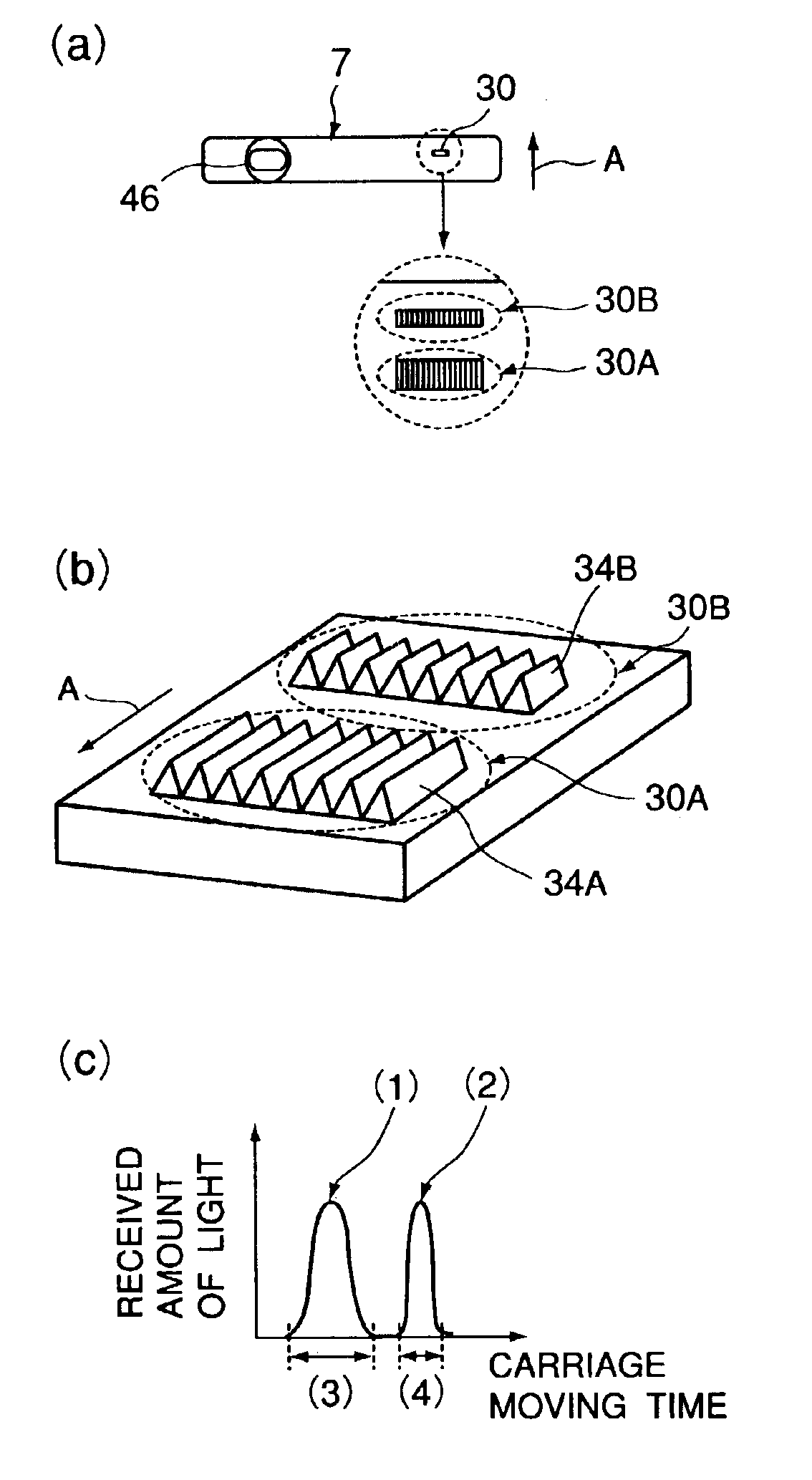
FIG. 9 is a schematic drawing for describing the first embodiment of a reflective member in accordance with the present invention. FIG. 9(a) is an enlarged view of the roof mirror portion of the reflective member on the bottom surface of an ink container and FIG. 9(b) is a perspective view of the roof mirror portion of the reflective member. FIG. 9(c) is a graph showing the distribution of the amount of the light received by the light receiving side when a liquid container has the first embodiment of a reflective member, in which the roof mirrors are positioned as shown in FIG. 9(b). It should be noted here that FIG. 9 is a perspective view, as seen from diagonally above, of the side of the reflective member, which faces inward of a liquid container as the reflective member is attached to the liquid container. Hereinafter, this embodiment of the present invention will be described in detail.

Referring to FIG. 9(a), the reflective member 30 has first and second roof mirr...

embodiment 2

(Embodiment 2)

This embodiment is a modification of the first embodiment; it is different from the first embodiment in that the first mirror unit is different in the roof mirror depth from the second mirror unit. Next, this embodiment will be described in detail.

FIG. 10 is a drawing for describing the second embodiment of a reflective member in accordance with the present invention. FIG. 10(a) is an enlarged view of the roof mirror portion of the reflective member on the bottom surface of an ink container, and FIG. 10(b) is a perspective view of the roof mirror portion of the reflective member. FIG. 10(c) is a graph showing the distribution of the amount of the light received by the light receiving side when a liquid container has the second embodiment of a reflective member, the roof mirrors of which are positioned as shown in FIG. 10(b).

Referring to FIG. 10(a), the reflective member 30 has first and second roof mirror units (reflective members) 30A and 30B, and is on the bottom wal...

embodiment 3

(Embodiment 3)

This embodiment is another modification of the first embodiment; it is different from the first embodiment in that the first mirror unit is different in the number of roof mirrors from the second mirror unit. Next, this embodiment will be described in detail.

FIG. 11 is a schematic drawing for describing the third embodiment of a reflective member in accordance with the present invention. FIG. 11(a) is an enlarged view of the roof mirror portion of the reflective member on the bottom surface of an ink container, and FIG. 11(b) is a perspective view of the roof mirror portion of the reflective member. FIG. 11(c) is a graph showing the distribution of the amount of the light received by the light receiving side when a liquid container has the third embodiment of a reflective member, in which the roof mirrors are positioned as shown in FIG. 11(b).

Referring to FIG. 11, the reflective member 30 has first, second, and third roof mirror units 30A, 30B, and 30C, and is on the b...


PUM


Abstract

A liquid container for containing liquid includes a reflection member having a plurality of roof mirror assemblies arranged in a predetermined direction, each of the roof mirror assemblies having at least two reflecting surfaces positioned with a predetermined angle therebetween; wherein the reflection member is effective to divide incident light into a plurality of light beams by the plurality of roof mirror assemblies and to condensing at a predetermined position the beams sequentially reflected by the at least two reflecting surfaces of the roof mirror assemblies; wherein the reflection member is effective to divide incident light into a plurality of light beams by the plurality of roof mirror assemblies and to condensing at a predetermined position the beams sequentially reflected by the at least two reflecting surfaces of the roof mirror assemblies.

Description

FIELD OF THE INVENTION AND RELATED ARTThe present invention relates to a liquid container equipped with an improved and preferable identifying means to be usable with a liquid-jet recording apparatus, for example, an ink jet recording apparatus. It also relates to a method for detecting the state of mount of a liquid container in a recording apparatus.There are various recording apparatuses which are capable of functioning as a printer, a copying machine, a facsimile machine, etc., and are usable as an output device for a compound electronic device, for example, a computer, a wordprocessor, a workstation, etc. These recording apparatuses are structured so that they record an image (inclusive of letters, symbol, etc.) on recording medium such as paper, fabric, plastic sheet, OHP sheet, etc., based on recording information. They may be classified into a plurality of types, based on their recording methods; for example, they can be classified into: ink jet type, wire dot type, thermal ...

Claims


Application Information

Patent Timeline
Patent Type & Authority Patents(United States)
IPC IPC(8): B41J2/175B65D25/20
CPCB41J2/17546B41J2/17566B41J2/1755B41J2/175
Inventor KOJIMA, YOSHINORITAKENOUCHI, MASANORIYAMAMOTO, HAJIMEIGAKI, MASAHIKOSHIMIZU, EIICHIROKOTAKI, YASUOKITABATAKE, KENJI
Owner CANON KK
Why Eureka
Try Eureka