Apparatus for moving a pair of opposing surfaces in response to an electrical activation

a technology of opposing surfaces and actuators, which is applied in the direction of electrical apparatus, piezoelectric/electrostrictive/magnetostrictive devices, piezoelectric/electrostriction/magnetostriction machines, etc., can solve the problems of reducing the effective life of the mechanism and the amount of force transferred through the hinge axes, so as to reduce the effective life of the mechanism and reduce the amount of force transferred , the effect of reducing the displacemen

Inactive Publication Date: 2005-03-22
PARKER INTANGIBLES LLC
View PDF210 Cites 29 Cited by
  • Summary
  • Abstract
  • Description
  • Claims
  • Application Information

AI Technical Summary

Benefits of technology

The present invention provides an apparatus for moving a pair of opposing surfaces in response to an electrical activation. The apparatus includes a support including a rigid non-flexing portion, first and second pivotable arm portions extending from the rigid portion, a pair of opposing surfaces with one opposing surface on each pivotable arm portion for movement relative to one another, and a force transfer member operably positioned between the first and second pivotable arm portions. An actuator is operably engaged between the rigid non-flexing portion and the force transfer member to drive the force transfer member in movement along a fixed path causing at least one of the first and second pivotable arm portions to pivot in response to an electrical activation of the actuator. The support and force transfer elements of the structure are designed to be rigid, non-flexing elements. Any unplanned flexing can reduce the effective life of the mechanism, and reduces the amount of force transferred through the hinge axes to pivot the arms. The reduction in force limits the displacement and force of the pivoting arms. The selection of the hinge axis location and corresponding structural configuration allows substantial capability to optimize the performance of the apparatus for the particular application.

Problems solved by technology

Any unplanned flexing can reduce the effective life of the mechanism, and reduces the amount of force transferred through the hinge axes to pivot the arms.

Method used


Image

  • Apparatus for moving a pair of opposing surfaces in response to an electrical activation
  • Apparatus for moving a pair of opposing surfaces in response to an electrical activation
  • Apparatus for moving a pair of opposing surfaces in response to an electrical activation

Examples


first embodiment

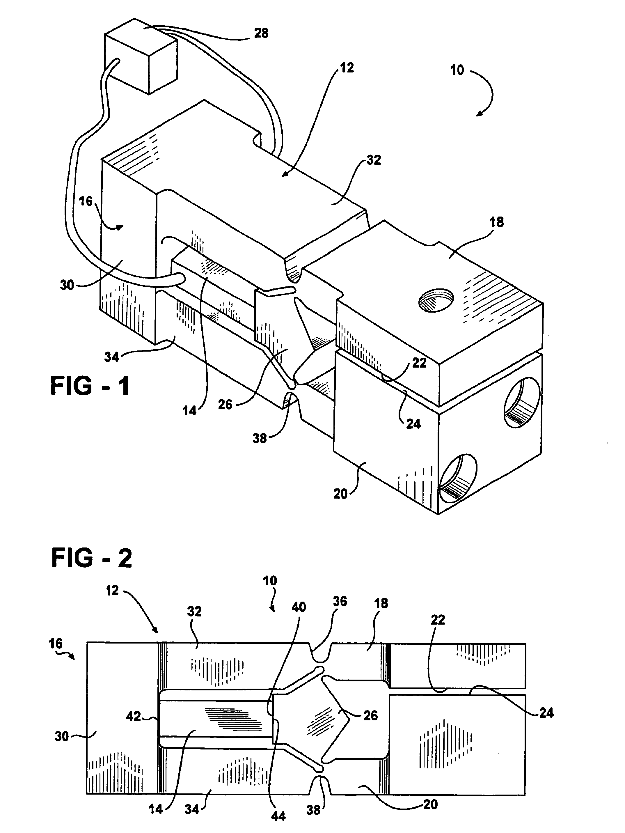
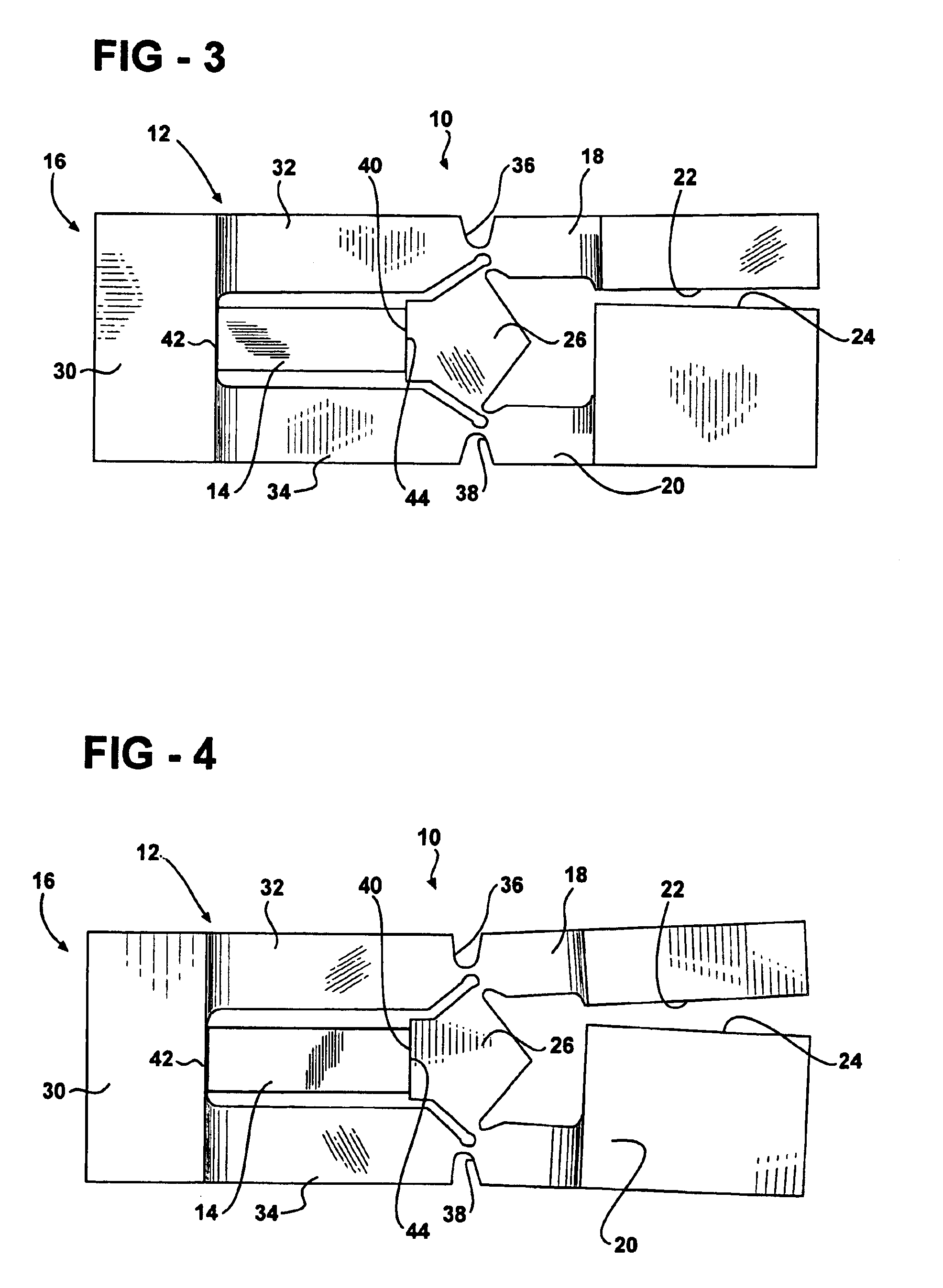
FIG. 2 is a side view of the apparatus 10. Preferably, the rigid, non-flexing portion 16 of the apparatus 10 is C-shaped including a rigid non-flexing web 30 extending between a pair of rigid non-flexing arm portions 32, 34. At least one pivotable arm portion 18 is pivotably connected via a living integral hinge 36 to one rigid arm portion 32. Another pivotable arm portion 20 can optionally be pivotably connected via a living integral hinge 38 to the other rigid arm portion 34, if two opposing pivotable arms are desired. The force transfer member 26 includes a seat surface 40.

The actuator 14 includes opposite ends 42 and 44 and, as described above, the actuator 14 produces a controlled spatial displacement between the opposite ends 42 and 44 in response to an electrical activation. One end 42 of the actuator 14, hereinafter referred to as the set or fixed end 42, is disposed adjacent to the rigid web 30. The other end 44 of the actuator 14, referred to hereinafter as the driving end...

second embodiment

FIG. 5 is the apparatus 10a with the force transfer member 26a having an alternative T-shape. The apparatus 10a includes a support 12a and an actuator 14a similar to that previously described for the other embodiments. The support 12a includes a rigid non-flexing portion 16a, at least one pivotable arm portion 18a, 20a extending from the rigid non-flexing portion 16a, a pair of opposing surfaces 22a, 24a with one opposing surface 22a, 24a on each pivotable arm portion 18a, 20a for movement relative to one another, and a force transfer member 26a operably positioned between the first and second pivotable arm portions 18a, 20a. Preferably, as with the other embodiments the entire support 12a is formed as a unitary, integral, single-piece body. The actuator 14a is operably engaged between the rigid portion 16a and the force transfer member 26a to drive the force transfer member 26a in linear motion away from the rigid web 30. Movement of the force transfer member 26a pivots the first a...

third embodiment

FIG. 6 is the apparatus 10b with an adjustable seat 52b supported by the rigid portion 16b with an adjustable support 54b. The apparatus 10b includes a support 12b and an actuator 14b similar to that previously described for the other embodiments. The support 12b includes a rigid non-flexing portion 16b, at least one pivotable arm portion 18b, 20b extending from the rigid non-flexing portion 16b, a pair of opposing surfaces 22b, 24b with one opposing surface 22b, 24b on each pivotable arm portion 18b, 20b for movement relative to one another, and a force transfer member 26b operably positioned between the first and second pivotable arm portions 18b, 20b. Preferably, as with the other embodiments the entire support 12b is formed as a unitary, integral, single-piece body. The actuator 14b is operably engaged between the rigid portion 16b and the force transfer member 26b to drive the force transfer member 26b in linear motion away from the rigid portion 16b. The rigid portion 16b supp...


PUM


Abstract

An apparatus for moving a pair of opposing surfaces in response to an electrical activation having a support including a rigid non-flexing portion, at least one pivotable arm portion extending from the rigid non-flexing portion, a pair of opposing surfaces with one opposing surface on the at least one pivotable arm portion for movement relative to one another, and a force transfer member operably positioned for driving the at least one pivotable arm portion in rotational movement. An actuator is operably engaged between the rigid portion and the force transfer member to drive the force transfer member in movement relative to the rigid portion to pivot the at least one pivotable arm portion with a loss of motion of less than 40% in response to an electrical activation of the actuator.

Description

FIELD OF THE INVENTIONThe present invention relates to an apparatus for moving a pair of opposing surfaces in response to an electrical activation.BACKGROUND OF THE INVENTIONVarious types of piezoelectric devices are known to those skilled in the art. Many of these devices include complex configurations and are very expensive to manufacture. Other devices include simpler configurations, but are extremely limited in the corresponding maximum range of movement or the corresponding maximum application of force.In such known devices, when the piezoelectric actuator is electrically activated, the rectangular prism geometry of the device expands predominantly along a predetermined axis. When the piezoelectric device is deactivated, the geometry of the device contracts predominantly along the predetermined axis. This expansion and contraction of the piezoelectric device can be used to operate an apparatus, e.g. to open and close a clamp or valve. An apparatus for clamping or valving typica...

Claims


Application Information

Patent Timeline
Patent Type & Authority Patents(United States)
IPC IPC(8): F16C11/12F16C11/04H01L41/09
CPCH02N2/043F16C11/12
Inventor MOLER, JEFF
Owner PARKER INTANGIBLES LLC
Why Eureka
Try Eureka