Docking apparatus

a technology of docking apparatus and docking head, which is applied in the direction of electronic circuit testing, measurement devices, instruments, etc., can solve the problems of not always enabling the docking of the testing head in the desired simple, easy and precise manner, and high cost, and achieves the effect of soft docking

Inactive Publication Date: 2005-03-22
MULTITEST ELEKTRONISCHE SYST
View PDF7 Cites 8 Cited by
  • Summary
  • Abstract
  • Description
  • Claims
  • Application Information

AI Technical Summary

Benefits of technology

According to an advantageous embodiment, the ball cage is axially displaceable with respect to the docking plate and has a limit stop surface for the locking pin. The limit stop surface is arranged in such a way that the circumferential groove of the locking pin abutting on the limit stop surface faces the balls. In this case, the ball cage is moved in an axial direction together with the balls by the locking pin itself until the ball cage has reached its axial end position. The movement of the ball cage is suitably carried out against the biasing force of a spring. This enables very soft docking, since the locking pin already inserted in the insertion guide does not abruptly impact on a fixed axial stop but the axial stop may still be displaced a bit further in the axial direction against the increasing force of a spring. In this way, also intermediate axial positions are possible, in which the locking pin has not yet been locked by the balls, however does experience a certain retention force, so that manual alignment of the, testing head is still possible without the risk of the locking pin being withdrawn from the insertion opening.
According to an advantageous embodiment, three locking units are provided on the docking plate, into each of which a locking pin is insertably mounted on the opposite device. A different number of locking units is easily possible, such as two, four or five locking units.

Problems solved by technology

It is, however, a drawback of such prior art docking devices that they do not always enable docking of the testing head in the desired simple, easy and precise manner and moreover are costly and have a complex structure.

Method used


Image

  • Docking apparatus
  • Docking apparatus
  • Docking apparatus

Examples


Embodiment Construction

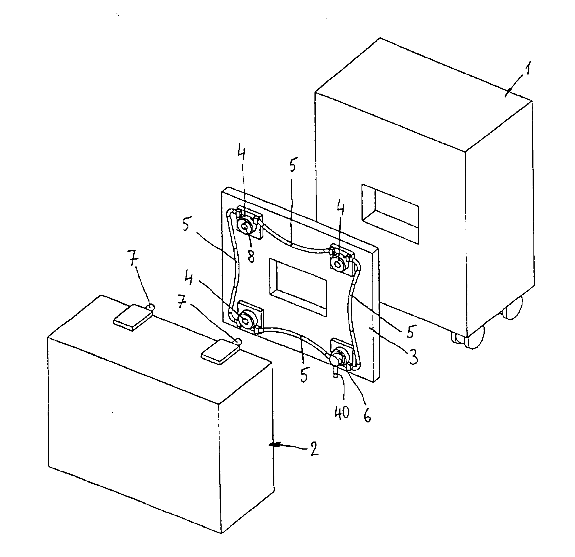
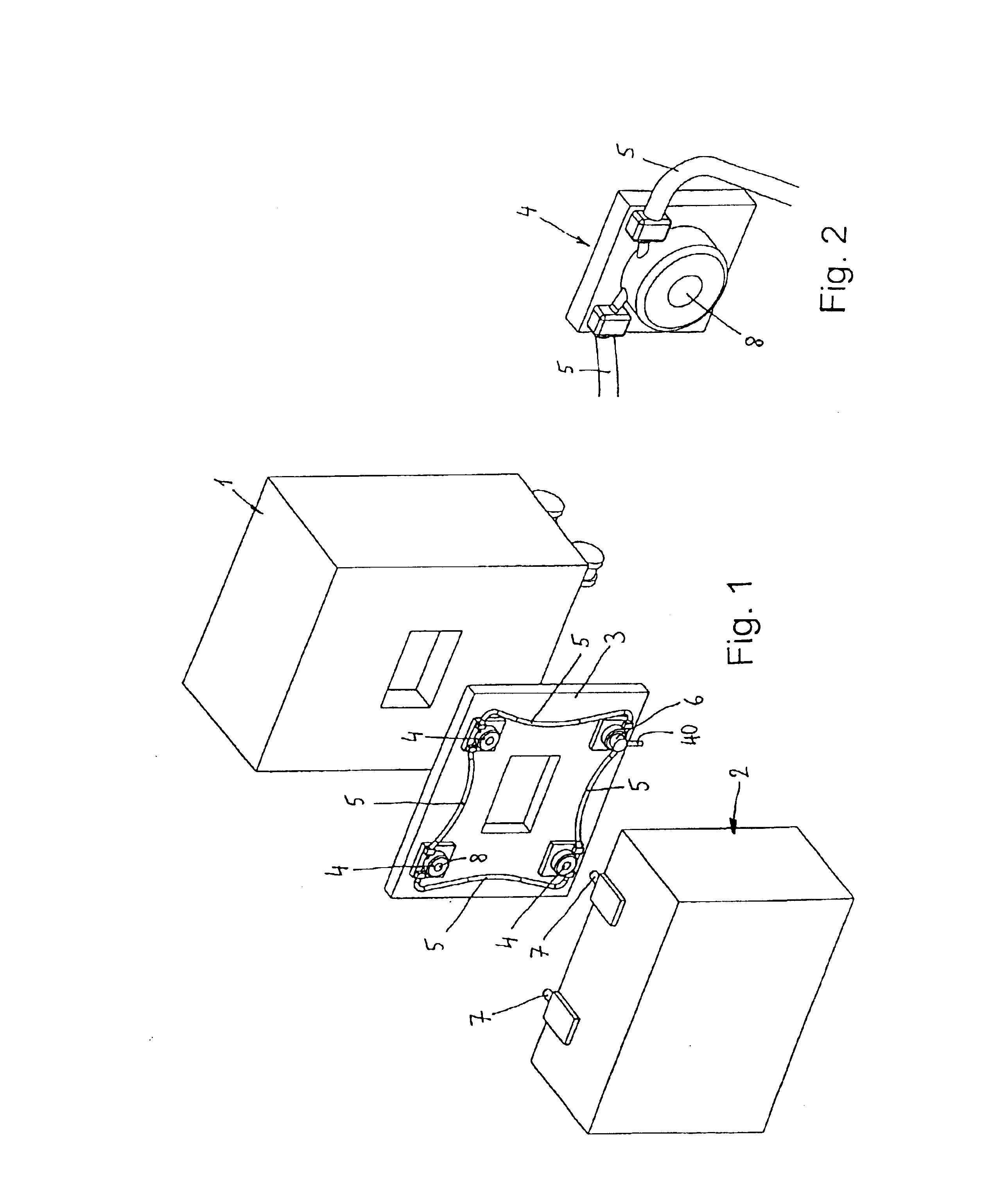
With reference to FIG. 1, a handling device 1 as well as a testing head 2 are shown. For docking the testing head 2 to the handling device 1, a docking plate 3 is used attachable either directly on the handling device 1 or on an intermediary frame (not shown), an overall number of three locking units 4 being attached on the docking plate 3. The locking units 4 are disposed in three corner areas of the docking plate 3 and mechanically coupled to a handling portion 6 via a Bowden wire means 5, the handling portion 6 being in the fourth corner of the docking plate 3.

Three locking pins 7 are attached on the testing head 2 and protrude beyond the testing head 2 and, as will be described in the following in more detail, are capable of being brought into engagement with the locking units 4.

The docking of the testing head 2 on the handling device 1 is done in such a way that first the testing head 2 is moved toward the handling device 1 or the docking plate 3 until the locking pins 7 are in...


PUM


Abstract

In a docking apparatus for coupling a first apparatus consisting of a handler or prober and a second apparatus consisting of a testing head for electronic components, at least one locking unit is provided having an axial insertion opening for inserting a locking pin. In the area of the insertion opening, a plurality of balls are arranged, between which the locking pin is insertable. Furthermore, a ball clamping sleeve is provided, which by means of an axial displacement causes a radial movement of the balls and therefore fixes the locking pin.

Description

CROSS-REFERENCE AND PRIORITY CLAIM TO RELATED APPLICATIONSTo the full extent permitted by law, the present application claims priority to and the benefit of German application, number 102 16 003.1, entitled “Dockingvorrichtung”, filed Apr. 11, 2002, wherein the application is incorporated herein by reference.BRIEF SUMMARY OF THE INVENTIONThe present invention refers to a docking apparatus for coupling a first apparatus consisting of a handler or prober with a second apparatus consisting of testing head for electronic components, according to the preamble of claim 1.BACKGROUND OF THE INVENTIONFor testing electronic components, such as integrated circuits (IC) it is known to use a testing apparatus having a testing head which must be connected to a handling device for the electronic component, such as a handler or prober. In order to facilitate docking of the testing head having a weight of up to 1000 kg to the handling device in a manner as simple, easy and precise as possible, speci...

Claims


Application Information

Patent Timeline
Patent Type & Authority Patents(United States)
IPC IPC(8): G01R31/28
CPCG01R31/2887G01R31/2851
Inventor THURMAIER, STEFAN
Owner MULTITEST ELEKTRONISCHE SYST
Why Eureka
Try Eureka