Barrier section connection system

a connection system and barrier section technology, applied in the direction of mechanical equipment, basic electric elements, couplings, etc., can solve the problems of uneven terrain, uneven connection, and inability to properly align and connect projections, and offer little structural resistance to impact for

Active Publication Date: 2014-10-21
VALMONT HIGHWAY TECH
View PDF116 Cites 9 Cited by
  • Summary
  • Abstract
  • Description
  • Claims
  • Application Information

AI Technical Summary

Benefits of technology

[0062]The inventors have found that one advantage of the present invention is that the configuration of the connection device allows the connection between two barrier sections to be placed in one position without altering the position of the downstream barrier connections. In prior art embodiments, re-positioning a joint between two barrier sections may result in other barrier sections also needing to be re-positioned or even resulting in other barrier sections falling apart and needing to be reassembled. A further advantage is that this connection provides support and stability to the barrier sections of the present invention in the event of a side on impact such as may occur in traffic applications.
[0063]Preferred embodiments of the present invention can have a number of advantages over the prior art which include providing a connection between at least two barrier sections to allow the sections to be retained fixed in either an in-line or at angled configuration. The present invention allows for simple readjustment to allow barrier sections to be re-configured in an angled position relative to each other. Further advantages include:
[0064]having a connection section(s) having few metal parts or elements that do not have to be checked for wear and tear;
[0065]a barrier connection assembly that can fasten and hold the sections together on uneven or sloped ground, therefore allowing the barrier to be constructed and be suitable for a number of different terrains; and
[0066]providing sufficient support between barrier sections so that upon impact, the connection device retains the relative position of the barrier sections.

Problems solved by technology

Alternatively, the barrier sections are connected by a series of four pins that fix the barrier sections in place and do not allow for any movement or pivoting between the sections.
One disadvantage of this system is the time taken to form this connection increases substantially when further barrier sections have already been connected together, as the user has to ensure that downstream barrier connections do not come apart when the section being worked on is lifted into place.
Additionally, as there is no locking or fastening mechanism in this connection, these types of barriers are generally only suitable for flat terrain.
Uneven terrain does not allow the projections to properly align and connect together.
A further disadvantage is that as sections are not locked together, this allows the sections to hinge and easily pivot with respect to each other, therefore offering little structural resistance to an impact force such as from a vehicle impact.
One problem with the connections described in NZ 511631 and NZ 524878 is that it is difficult to move a barrier section into a different orientation to the other sections.
The hinging mechanisms can not be easily re-positioned from the initial arrangement.
This can be time consuming and labour intensive, as numerous parts have to be manipulated.
Another disadvantage is that the hinging connections are constructed from metal.
Also to avoid corrosion, the metal needs to be resistant to corrosion and hence tends to add expense to the barrier cost.
Further, as the hinge elements or brackets project out from the end of the barrier section, this may be a potential hazard particularly if the barrier is struck by an impacting vehicle, as substantial damage may be caused to the vehicle and / or passages.

Method used


Image

  • Barrier section connection system
  • Barrier section connection system
  • Barrier section connection system

Examples


Embodiment Construction

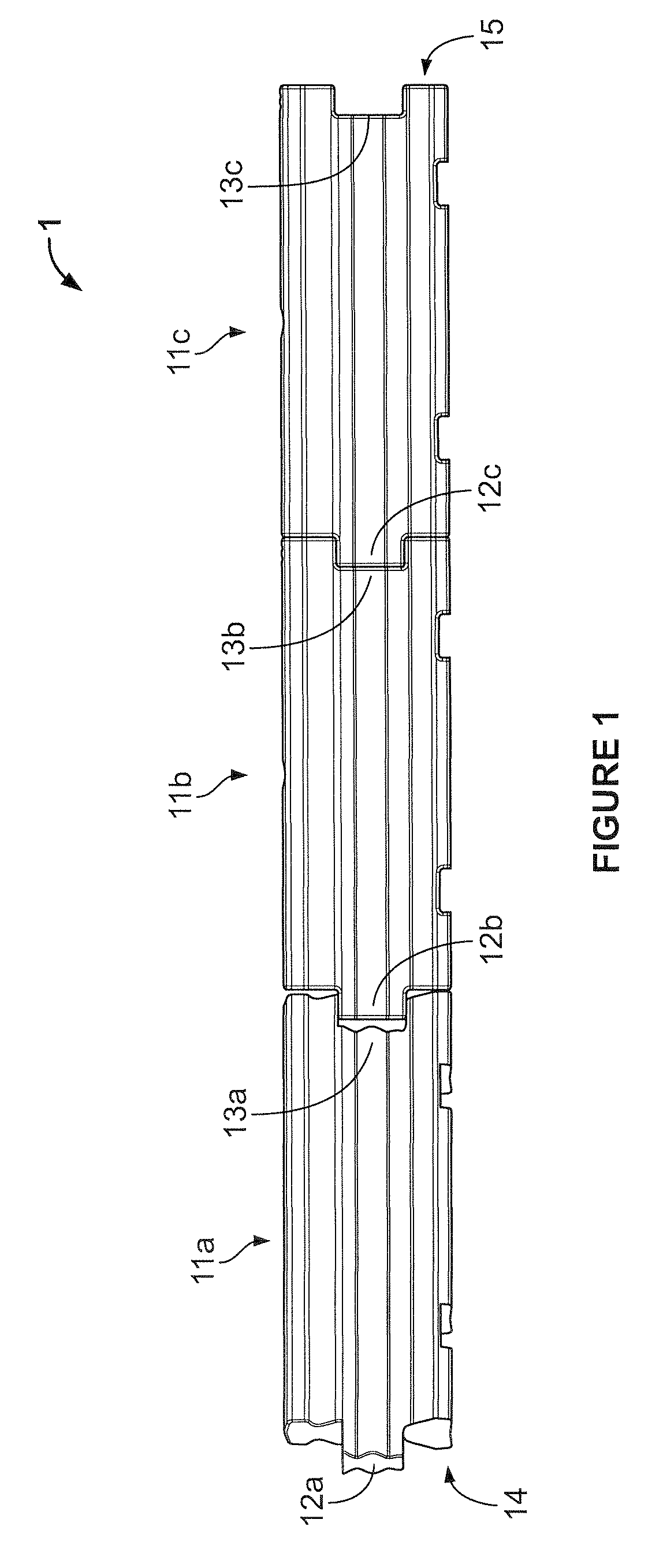
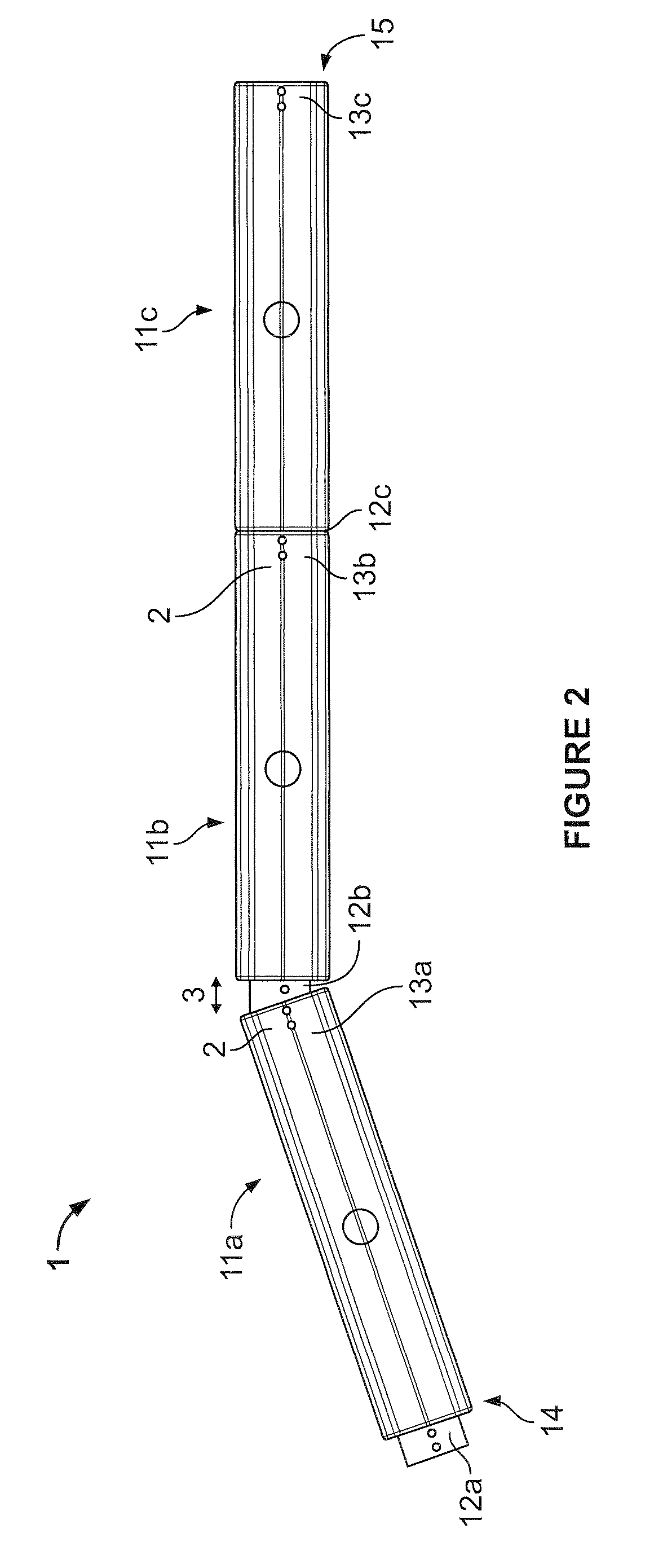
[0083]FIGS. 1, 2 and 9 show a barrier 1. The barrier 1 is constructed from three barrier sections, as indicated by arrows 11a to 11c respectively. In FIG. 2 the two ends of the barrier sections 11a and 11b are orientated in a second position, while two ends of the barrier sections 11b and 11c are orientated in a first position. When the barrier sections are orientated in a first position, (for example, the barrier sections 11b and 11c) the barrier sections are positioned in an in-line position with respect to each other. In comparison, when the barrier sections are orientated in a second position, one barrier section 11a, is positioned in an angled position with respect to the second barrier section 11b.

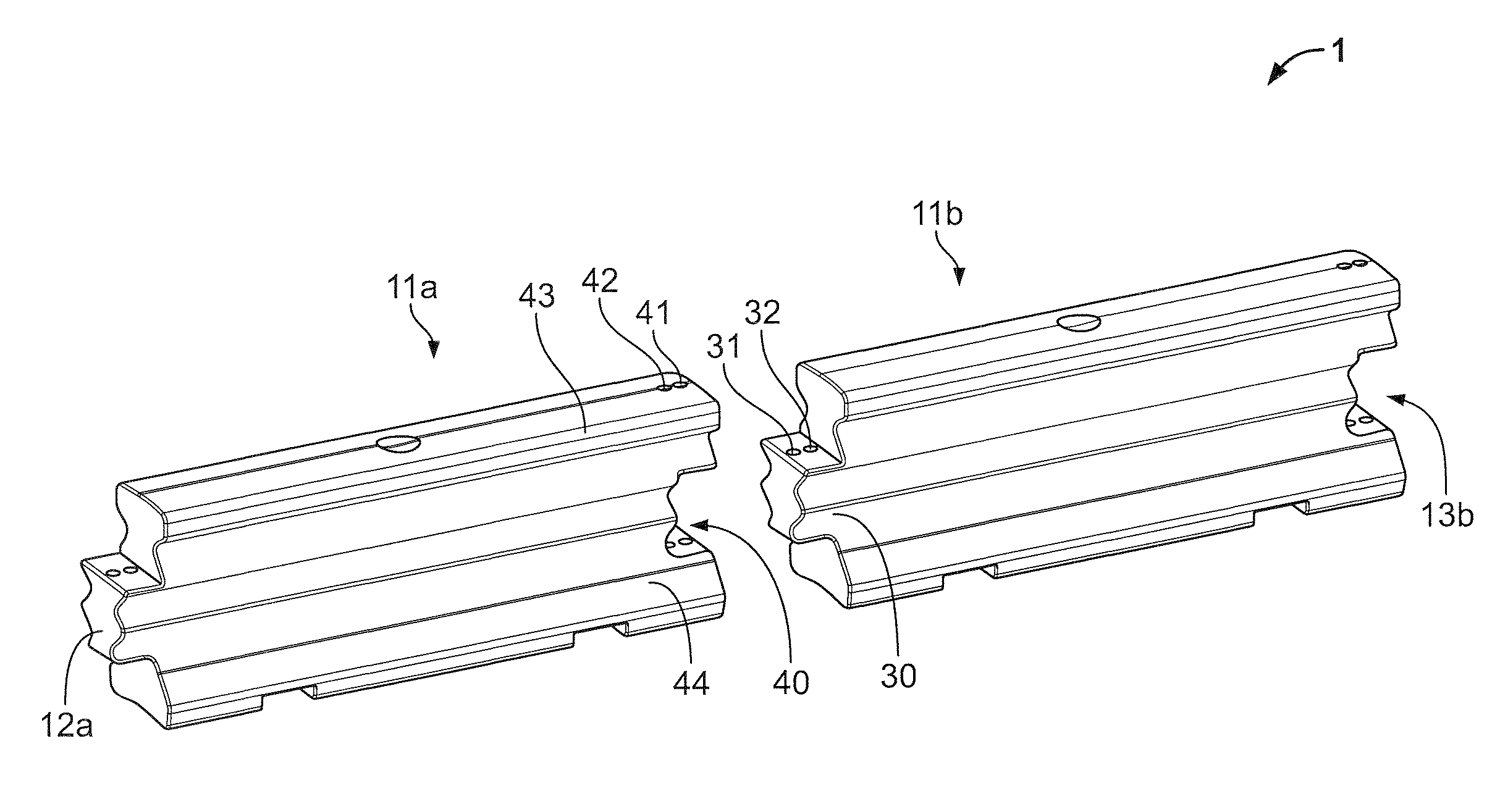
[0084]FIGS. 3 and 4 respectively show a side view and plan view of a single barrier section 11. As shown, the barrier section 11 has a projection 12 in the form of a single protrusion 30 at one end 14 of the barrier section 11. Additionally, the barrier section 11 has a receiving po...


PUM


Abstract

A barrier section which includes at least one connecting assembly at one or both ends of the barrier section, the connecting assembly having: at least one connecting-region which is positioned to be capable of engaging, or being engaged, with at least one connecting-region on an adjacent barrier section, in use; and the at least one connecting-region is configured to selectively engage with at least one connecting-region on an adjacent barrier section via at least one connecting device so the barrier sections have a fixed or pivotable relationship, with one another.

Description

STATEMENT OF CORRESPONDING APPLICATIONS[0001]This application is based on the provisional specification filed in relation to New Zealand Patent Application Number 555598, the entire contents of which are incorporated herein by reference.TECHNICAL FIELD[0002]The invention relates to an improved barrier section. In particular, the present invention relates to improved barrier section and connection system between two or more barrier sections. The connection system allows the barrier sections to be aligned and retained in at least two different configurations when forming the barrier.BACKGROUND ART[0003]There are a number of different types of permanent and temporary barriers. These barriers are used in a number of applications where it is necessary to separate one area from another. Examples of the types of applications barriers may be used include, dividing road lanes, construction sites or other hazardous areas.[0004]Barriers are typically constructed by connecting a plurality of ba...

Claims


Application Information

Patent Timeline
Patent Type & Authority Patents(United States)
IPC IPC(8): E04H17/14E01F15/08
CPCE01F15/086E01F15/085E01F15/088Y10T403/32951Y10T403/32606
Inventor JAMES, DALLAS
Owner VALMONT HIGHWAY TECH
Why Eureka
Try Eureka