Image processing apparatus, method of image processing, print control apparatus, and recording media

a technology of image processing and print control, applied in the field of image data conversion, can solve the problems of wasting processing time, storing tone expression errors, and distributing tone expression errors, and achieve the effects of high-speed display of high-quality images, shortening processing time, and improving picture quality

Inactive Publication Date: 2005-03-22
SEIKO EPSON CORP
View PDF4 Cites 7 Cited by
  • Summary
  • Abstract
  • Description
  • Claims
  • Application Information

AI Technical Summary

Benefits of technology

The object of the present invention is thus to provide a technique of shortening the processing time required for determination of the dot on-off state while keeping the picture quality at an eq

Problems solved by technology

The error diffusion method diffuses and stores an error of tone expression, which arises in a pixel of interest due to creation of a dot or creation of no dot in the pixel, into peripheral non-processed pixels in the vicinity of the pixel of interest.
The least mean square error method, on the other hand, stores the error of tone expression, which arises due to the determination of the dot on-off state, in the pixel of interest without diffusion into peripheral non-processed pixels.
The process of

Method used


Image

  • Image processing apparatus, method of image processing, print control apparatus, and recording media
  • Image processing apparatus, method of image processing, print control apparatus, and recording media
  • Image processing apparatus, method of image processing, print control apparatus, and recording media

Examples


first embodiment

B. First Embodiment

B-1. Construction of System

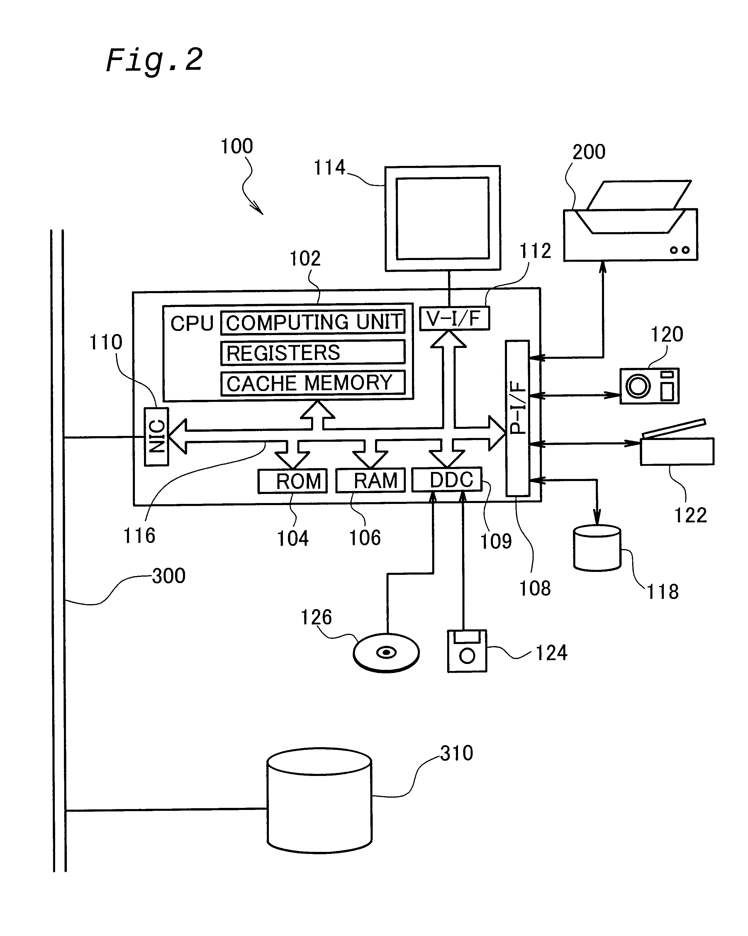
FIG. 2 schematically illustrates the construction of a computer 100 as an image processing apparatus in a first embodiment. The computer 100 has a known structure including a CPU 102, a ROM 104, and a RAM 106 that are mutually connected via a bus 116. The CPU 102 has a computing unit that actually executes processing and a plurality of registers that temporarily keep data being processed. The data kept in the registers can be processed at a significantly higher speed than data stored in the RAM 106. A special storage element called a cache memory may be applied, in place of the registers. The cache memory allows higher-speed reading and writing operations of data than the RAM 106, although not so high as the register. The cache memory can treat a greater quantity of data than the register.

The computer 100 is connected to a disk controller DDC 109 for reading data from a floppy disk 124 and a compact disc 126, a peripheral equipment inter...

second embodiment

C. Second Embodiment

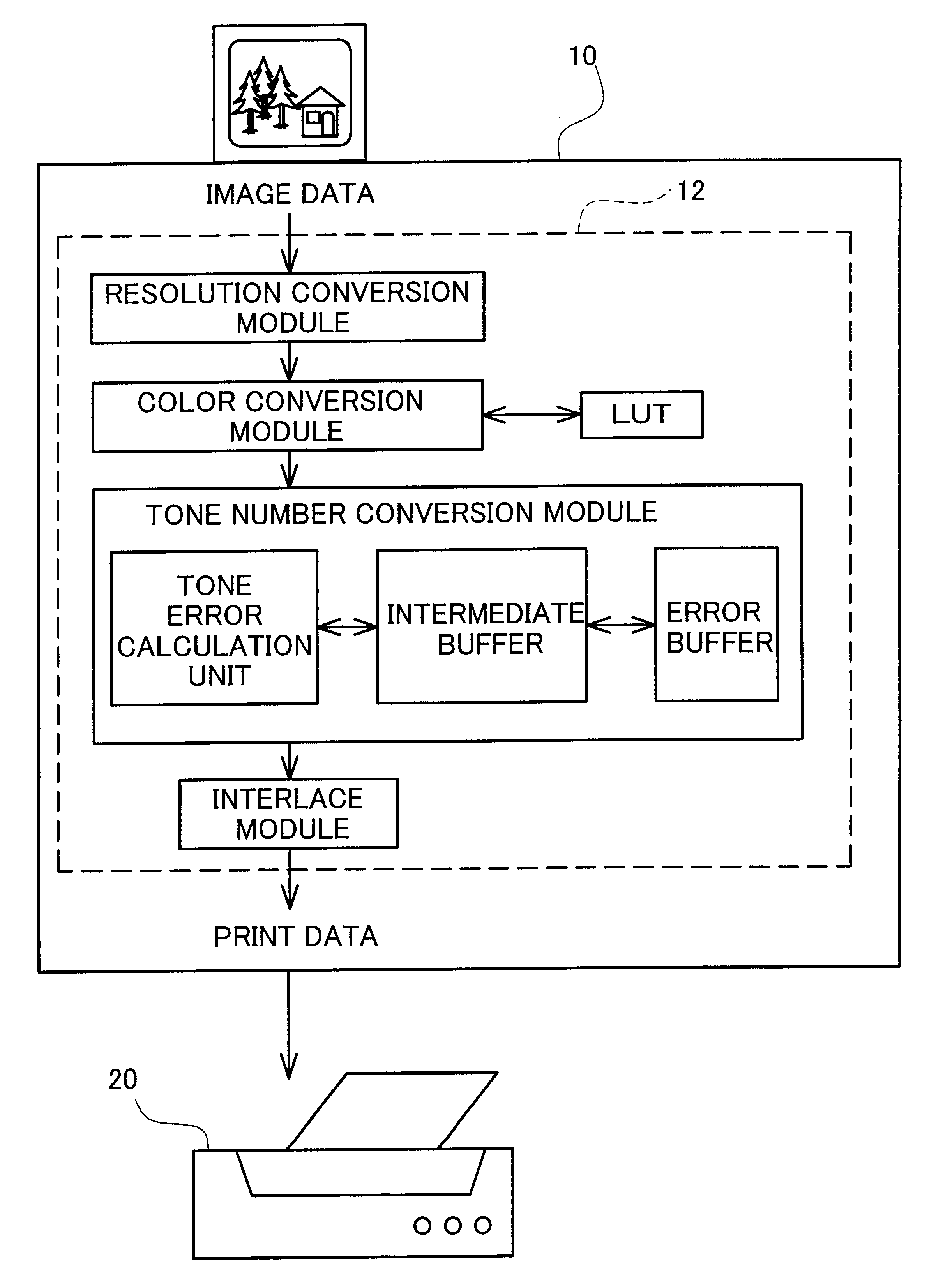
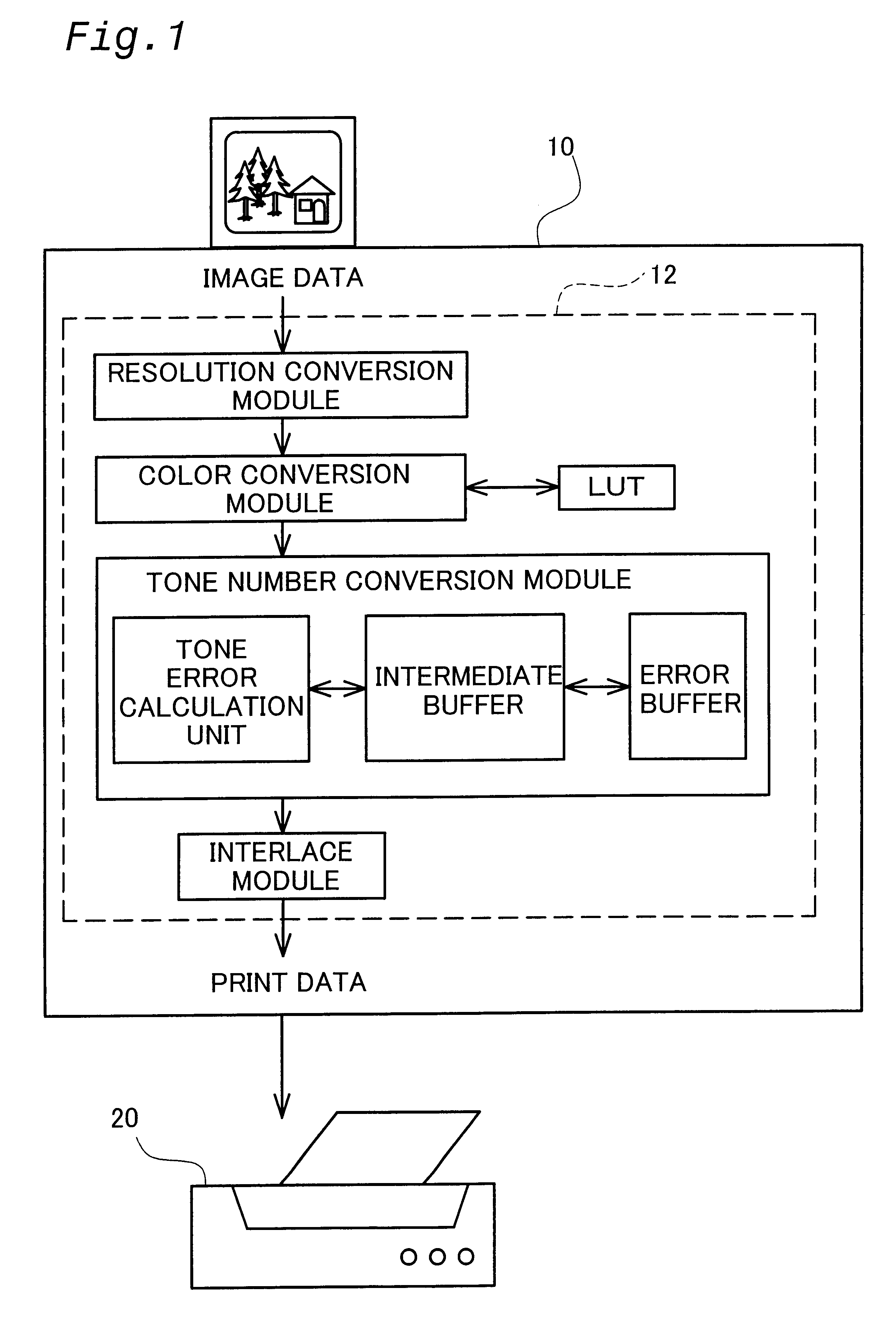
C-1. Principles of Shortening Time Required for Tone Number Conversion Process in Second Embodiment

The tone number conversion process of the first embodiment discussed above diffuses the tone error, which arises due to determination of the dot on-off state, into the intermediate buffer like registers that allow high-speed reading and writing operations. The process writes all the error divisions, which are diffused in the intermediate buffer, into the error buffer every time determination of the dot on-off state is concluded for a preset number of pixels. Another tone number conversion process executed in a second embodiment discussed below, on the other hand, writes the error divisions with regard to one pixel into the error buffer every time determination of the dot on-off state is concluded for one pixel. As discussed below, the method of the second embodiment requires a less number of registers to implement the tone number conversion process, compared with th...

third embodiment

D. Third Embodiment

The embodiments discussed above use an identical error diffusion matrix for error diffusion. In the actual tone number conversion, however, in order to attain the desired picture quality, the procedure may selectively use an error diffusion matrix having a narrower diffusion range as in the case of FIG. 6(a) and another error diffusion matrix having a wider diffusion range as in the case of FIG. 6(c).

The error diffusion method may change over the selection among multiple error diffusion matrixes at random, in order to prevent formation of dots in a specific periodical pattern. The technique disclosed in JAPANESE PATENT LAID-OPEN GAZETTE No. 7-226841 uses an error diffusion matrix having a wide diffusion range for error diffusion to improve the dispersibility of dots in a lower dot density area, when the tone value of image data is smaller than a sufficiently small preset threshold value and results in determining creation of a dot. The reason why such application ...


PUM


Abstract

The technique of the present invention temporarily registers a tone error, which arises in each pixel due to determination of the dot on-off state in the pixel, in an intermediate buffer. The technique calculates diffusion errors or error divisions, which are diffused to each of non-processed pixels in a neighborhood of a preset number of pixels, from tone errors arising in the preset number of pixels, and writes the error divisions into an error buffer. One procedure diffuses each tone error into the intermediate buffer in response to every occurrence of the tone error, and subsequently writes the diffused error divisions into the error buffer. Another procedure registers tone errors arising in the preset number of pixels in the intermediate buffer and writes the error divisions, which are calculated from the registered tone errors with regard to the preset number of pixels, into the error buffer. Compared with the conventional technique that diffuses each tone error into the error buffer in response to every occurrence of the tone error, either of these procedures enables collective diffusion of the tone errors with regard to the preset number of pixels, thus ensuring higher-speed diffusion of the tone error. The error diffusion may be attained by utilizing a procedure mathematically equivalent to the least mean square error method.

Description

BACKGROUND OF THE INVENTION1. Field of the InventionThe present invention relates to a technique of converting image data that are expressed by tone values of pixels constituting an image. More specifically the present invention pertains to a technique of converting the image data into a specific expression format based on the dot on-off state of each pixel.2. Description of the Related ArtImage display devices that create dots on a display medium, such as a printing medium or the screen of a liquid crystal display, to express an image are widely used as output devices of diverse image devices. The image display device takes only either the dot on state or the dot off state as local expression, but enables display of an image of s continuously varying tone by adequately adjusting the dot formation density according to the tone values of an original image.Typical techniques applied for such image display devices to determine the dot on-off state in each pixel and ensure dot creation ...

Claims


Application Information

Patent Timeline
IPC IPC(8): H04N1/405B41J2/52G06F3/12G06T5/00H04N1/40
CPCH04N1/4052G06F3/12
Inventor KAKUTANI, TOSHIAKI
Owner SEIKO EPSON CORP
Why Eureka
Try Eureka