
Communication apparatus

a technology of communication apparatus and communication circuit, which is applied in the direction of electrical apparatus, radio transmission, transmission, etc., can solve the problems of long synchronization-acquisition time, complicated hardware, and drawbacks of the above-described conventional system, and achieve the effect of increasing transmission capacity

Inactive Publication Date: 2005-03-22
CANON KK
View PDF8 Cites 11 Cited by
  • Summary
  • Abstract
  • Description
  • Claims
  • Application Information

AI Technical Summary

Benefits of technology

Accordingly, it is an object of the present invention to increase transmission capacity.
Yet another object of the present invention is to reduce the data error rate.
A further object of the present invention is to maintain the transmission rate regardless of increased traffic.

Problems solved by technology

The above-described conventional system has drawbacks, complicated hardware as well as long synchronization-acquisition time.
When there are a plurality of hopping patterns and a plurality of radio communication channels, the same frequency may be used at the same time for different transmissions, increasing the data error rate.
Due to these drawbacks, frequency-hopping multiple access could not be readily implemented.
As a result, it was difficult to use available frequencies efficiently, and it is hard to configure a system having large transmission capacity.

Method used


Image

  • Communication apparatus
  • Communication apparatus
  • Communication apparatus

Examples


second embodiment

A second embodiment according to the present invention will be described below.

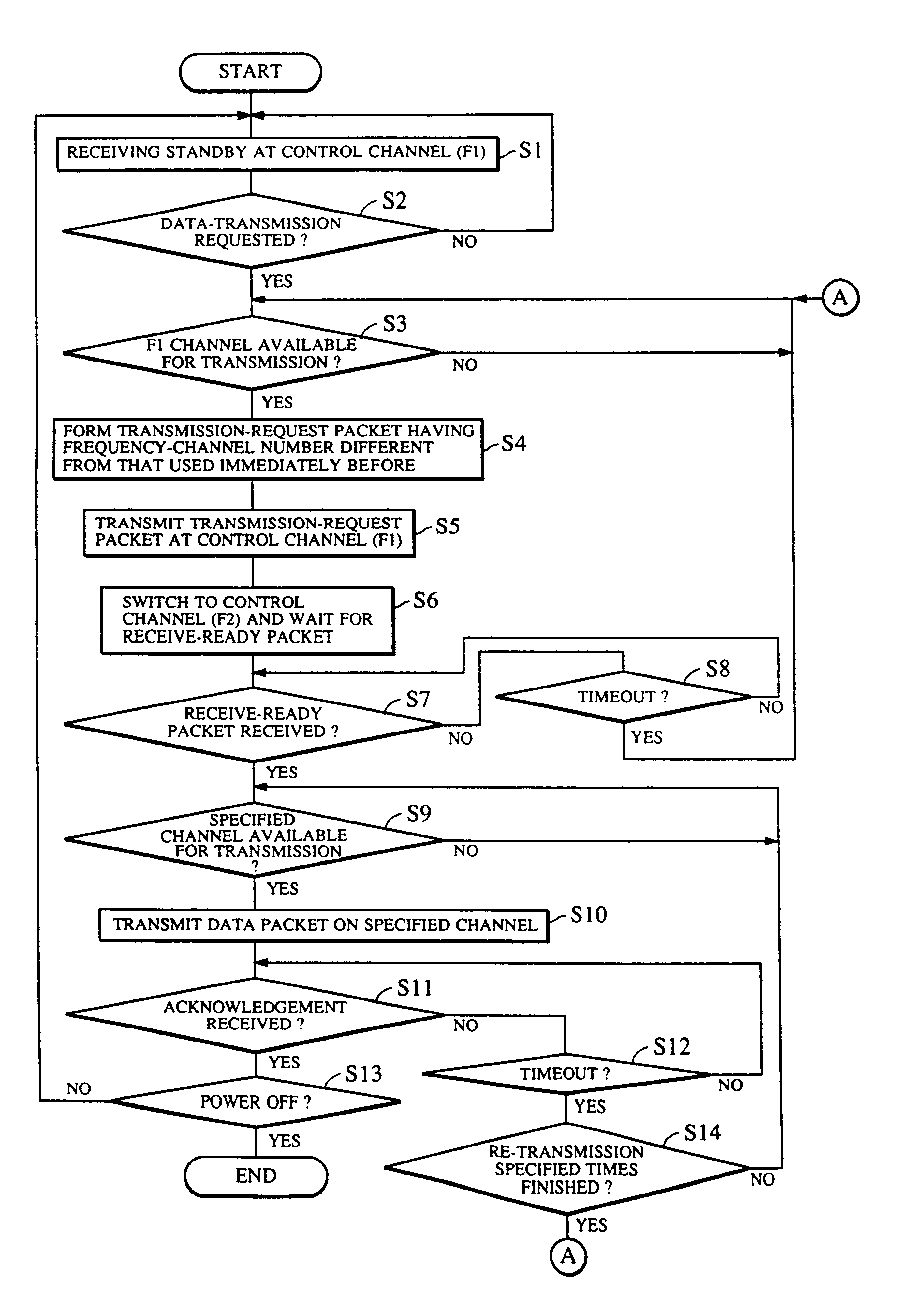
In the first embodiment described above, a control channel is used to specify a frequency channel to be used for transmitting a data packet before the data packet is sent. When packets are successively transmitted, control channels can be less frequently used by inserting data specifying a channel to be used for the next packet and its packet number in the current data packet to be sent, as shown in FIG. 9. FIG. 10 illustrates the use of channels in this case.

Errors can be controlled with a usual selection re-transmission method because each data packet has its packet number. If the receiving side finds an error, only the packet in which the error has been found is transmitted again.

Employing these methods reduces times control channels are used and further increases the system throughput.

third embodiment

A third embodiment according to the present invention will be described below.

In the embodiments described above, data to be sent is transmitted on a radio line without any processing. When processing, such as adding error correction codes, is applied to data to be sent, however, the same advantages are obtained. In addition, reduction in data errors further increases actual transmission capacity.

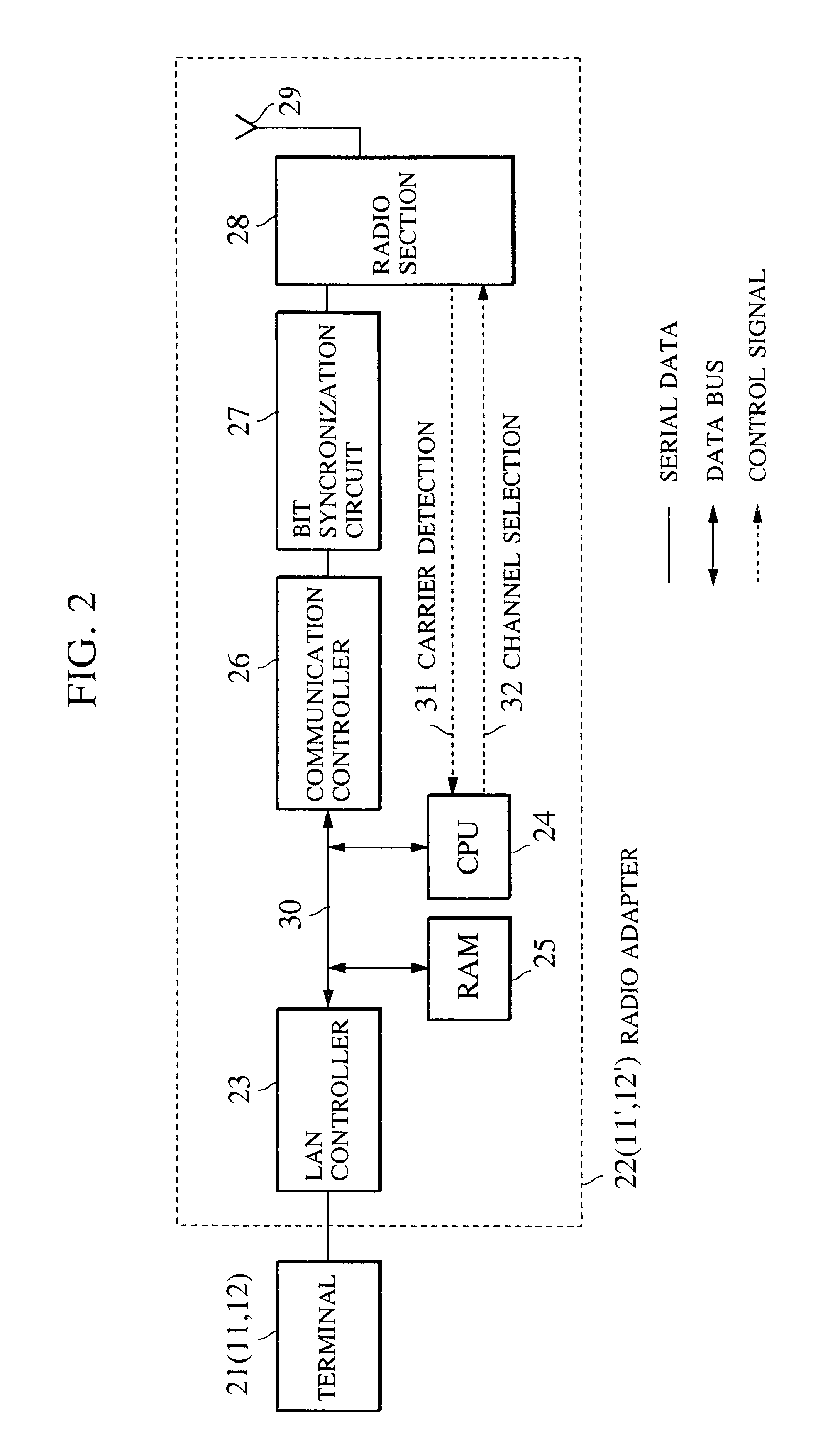
FIG. 11 is a block diagram of the configuration of the radio adapter 22′ in this embodiment. As shown in FIG. 11, an encoder and decoder 30 for error correction codes is added to the radio adapter described in the first embodiment (shown in FIG. 2).

FIG. 12 shows the format of a radio frame according to this embodiment. As shown in FIG. 12, additional data items for error correction processing are added.

In the configuration described above, when a data transmission request occurs, data is stored in RAM 25 and a transmission request is sent through a control channel, in the same way as the fi...


PUM


Abstract

In a communication system using frequency hopping to transmit data packets, a transmission request from a transmitter is transmitted through a first control channel. The transmission request includes a frequency channel designation selecting one of plural data channels. A receiver that receives the transmission request sends a receive confirmation through a second control channel and the data packets are then transmitted through the data channels so that the data channel is changed each time a data packet is transmitted.

Description

BACKGROUND OF THE INVENTION1. Field of the InventionThe present invention relates to a communication apparatus which communicates through a plurality of data transmission channels.2. Description of the Related ArtIn these days, the demand for digital-radio data communication has been increasing. To respond to the demand, spread spectrum communication, which is one of digital-radio communication methods, has been used. In spread spectrum communication, slow frequency hopping has frequently been used due to its simplified configuration.In slow frequency hopping, the used frequency is changed for each set of a plurality of data bits to reduce effects of narrow-band noise when data is re-transmitted if an error occurs, and to obtain a frequency-diversity effect. However, the sending and receiving sides are required to be synchronized to effect frequency switching.Conventionally, to get synchronization, the receiving side slightly converts the phase of a hopping pattern until the phases ...

Claims


Application Information

Patent Timeline
IPC IPC(8): H04B1/69H04B1/713H04B1/7143H04B1/715
CPCH04B1/7143H04B2001/7154
Inventor IZUMI, MICHIHIRO
Owner CANON KK
Learn More